- contact us
- Sales Manager:
Asia Li - Email:
asia.cncmachine@gmail.com - Wechat ID:
Asia-Li_90727( +8613210773378) TEL:+8613210773378 - TEL:
8613210773378 - Whatsapp:
8613210773378

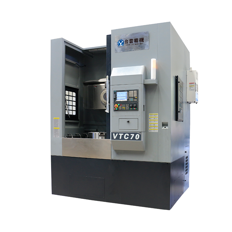
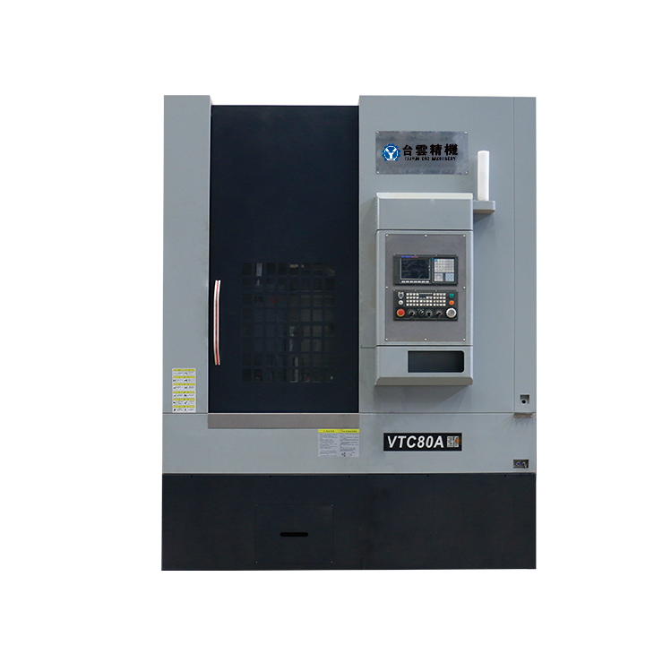
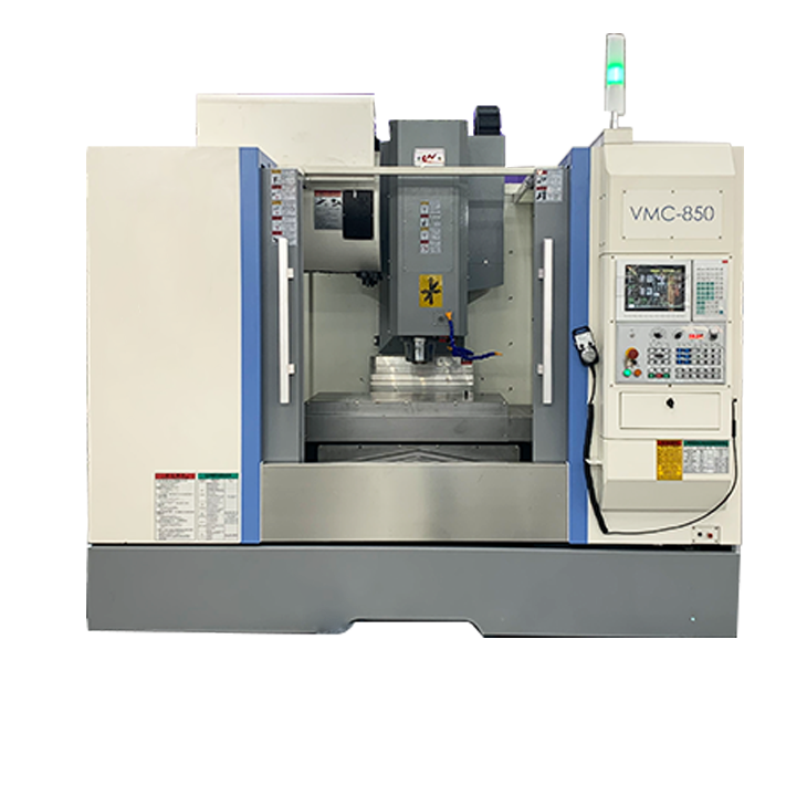
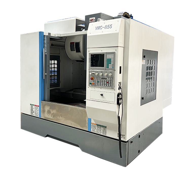
High speed machining center
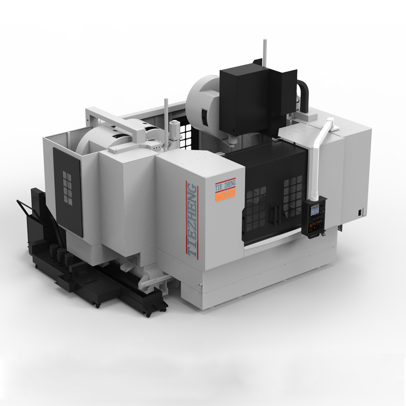
High-speed machining center is an important equipment in the mold manufacturing industry, which can achieve efficient and high-precision processing....
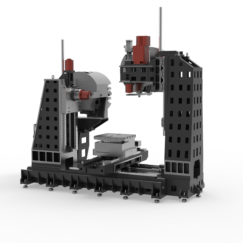
High-speed machining center is an important equipment in the mold manufacturing industry, which can achieve efficient and high-precision processing. With the continuous advancement of drive technology, high-speed machining centers have continued to innovate in structure and their performance has been significantly improved. At present, high-speed machining centers have developed from servo motors and ball screw drives for linear motion to linear motor drives, and direct-drive torque motors are used for rotary motion. This transformation significantly improves the machining center's stroke speed, dynamic performance and positioning accuracy.
The working principle of the high-speed machining center mainly relies on the high-speed rotating spindle, multi-axis linkage and advanced control algorithms, which enables the machine tool to achieve fast and precise cutting during the processing process, while ensuring excellent surface quality and good processing stability.
In terms of processing capabilities, high-speed machining centers have the characteristics of high maximum processing size of workpieces and high precision. Different high-speed machining center equipment differs in processing capabilities. For example, some equipment may have a larger processing size range and higher processing accuracy.
High-speed machining centers have a wide range of applications and are suitable for processing a variety of workpieces. For example, high-speed machining centers can be used to process box-shaped workpieces, complex curved workpieces, irregular parts, and plates, sets, and plate-type workpieces. In addition, high-speed machining centers can also perform special processing, such as quenching treatment on metal surfaces.
Looking to the future, high-speed machining centers will develop in a more intelligent, efficient and precise direction. With the continuous advancement of technology, high-speed machining centers will provide more flexible tool and fixture systems to meet the needs of different processing tasks. At the same time, the application of multi-axis machining technology, advanced tool materials and coating technology, and intelligent manufacturing technology will further promote the development of high-speed machining and improve machining efficiency and machining accuracy.
Therefore, when selecting a high-speed machining center, it is recommended to comprehensively consider it based on actual needs, budget, and workpiece characteristics. At the same time, it is also necessary to pay attention to the professionalism and complexity of operating and maintaining high-speed machining centers to ensure the normal operation of the equipment and processing quality.
| Specifications/model | unit | VW50A | VW63A | VW80A | VW50C | VW63B | VW80B | VW50C | VW63C | VW80C | VW63D | VW80D | VW100D |
| Spindle position result | Same side of the cross | Same side of the cross | Same side of the cross | Same side of the cross | Same side of the cross | Same side of the cross | Contralateral simultaneous processing | Contralateral simultaneous processing | Contralateral simultaneous processing | Inverted T-shaped same side | Inverted T-shaped same side | Inverted T-shaped same side | |
| Work content | |||||||||||||
| Horizontal X (left and right), Y (up and down), Z (front and back) | CM | 80、55、550 | 110、60、60 | 130、80、70 | 80、60、50 | 110、80、70 | 130、90、80 | 80、60、50 | 110、80、70 | 130、90、80 | 105、80、60 | 160、80、70 | 200、90、80 |
| Vertical X (left and right), Y (front and back), Z (up and down) | CM | 80、55、550 | 110、60、55 | 130、70、70 | 80、60、60 | 110、70、70 | 130、80、90 | 80、60、60 | 110、70、70 | 130、80、80 | 105、70、70 | 160、80、80 | 200、80、90 |
| Workbench area (can be customized) | MM | 500×500 | 630×630 | 800×800 | 500×500 | 630×630 | 800×800 | 500×500 | 630×630 | 800×800 | 630×630 | 800×800 | 1000×1000 |
| Maximum load | KG | 600 | 800 | 1500 | 600 | 1100 | 1800 | 600 | 1100 | 1800 | 1200 | 1800 | 2200 |
| T-shaped slot (slot width × number of slots) | MM | 18×3 | 20×3 | 22×5 | 18×3 | 22×3 | 22×5 | 18×3 | 22×3 | 22×5 | 22×5 | 28×5 | 28×7 |
| Standard dividing angle of workbench | ℃ | any equal portion | any equal portion | any equal portion | any equal portion | any equal portion | any equal portion | any equal portion | any equal portion | any equal portion | any equal portion | any equal portion | any equal portion |
| Workbench split angle (customized) | ℃ | 1、5、90 | 1、5、90 | 1、5、90 | 1、5、90 | 1、5、90 | 1、5、90 | 1、5、90 | 1、5、90 | 1、5、90 | 1、5、90 | 1、5、90 | 1、5、90 |
| Processing range | |||||||||||||
| Distance from horizontal spindle center to worktable | -200+500 | -200+600 | -200+800 | +50-650 | +50-850 | +50-950 | +50-650 | +50-850 | +50-950 | -200+600 | -200+700 | -200+800 | |
| Horizontal spindle nose to the side of the workbench | MM | +100-450 | +100-500 | +100-600 | +100-500 | +150-550 | +200-600 | +100-50 | +150-550 | +200-600 | +100-500 | +100-600 | +100-700 |
| Distance from vertical spindle nose to work surface | MM | +200+750 | +200+800 | +200+900 | +150-750 | +150-850 | +150-1050 | +150-750 | +150-850 | +150-1050 | +200+800 | +200+1000 | +200+1100 |
| Maximum height/diameter of workpiece | MM | 500/900 | 600/1300 | 800/1500 | 500/900 | 600/1300 | 800/1500 | 500/900 | 600/1300 | 800/1500 | 700/900 | 800/1300 | 900/1500 |
| Spindle content | |||||||||||||
| handle form | / | BT40 | BT40 | BT50 | BT40 | BT50 | BT50 | BT40 | BT50 | BT50 | BT50 | BT50 | BT50 |
| Maximum speed of vertical and horizontal spindles | RPM | 8000 | 8000 | 6000 | 8000 | 6000 | 6000 | 8000 | 6000 | 6000 | 6000 | 6000 | 6000 |
| Maximum speed of vertical and horizontal spindle (optional) | RPM | 12000 | 12000 | 6000 | 12000 | 6000 | 6000 | 12000 | 6000 | 6000 | 6000 | 6000 | 6000 |
| Tool magazine content | / | ||||||||||||
| horizontal structure | / | Robotic arm | Robotic arm | Robotic arm | Robotic arm | Robotic arm | Robotic arm | Robotic arm | Robotic arm | Robotic arm | Robotic arm | Robotic arm | Robotic arm |
| Maximum tool diameter | MM | 350 | 350 | 350 | 350 | 350 | 350 | 350 | 350 | 350 | 350 | 350 | 350 |
| Maximum tool weight | KG | 8 | 8 | 15 | 8 | 15 | 15 | 8 | 15 | 15 | 15 | 15 | 15 |
| Number of horizontal and vertical tools | T | 24/24 | 24/24 | 24/24 | 24/24 | 24/24 | 24/24 | 24/24 | 24/24 | 24/24 | 24/24 | 24/24 | 24/24 |
| Three-axis rapid traverse speed | M/MIN | 32/32/32 | 32/32/32 | 24/24/24 | 32/32/32 | 32/32/32 | 24/24/24 | 32/32/32 | 32/32/32 | 24/24/24 | 32/32/32 | 24/24/24 | 24/24/24 |
| Axis servo motor | |||||||||||||
| Spindle motor horizontal/vertical | KW | 11/11 | 11/11 | 18.5/18.5 | 11/11 | 18.5/18.5 | 18.5/18.5 | 11/11 | 18.5/18.5 | 18.5/18.5 | 18.5/18.5 | 18.5/18.5 | 18.5/18.5 |
| X, Y, Z axis, B | NM | 22/22/22/12 | 22/22/22/22 | 27/27/27/22 | 22/22/22/22 | 27/27/27/22 | 27/27/27/22 | 22/22/22/22 | 27/27/27/22 | 27/27/27/22 | 27/27/27/22 | 27/27/27/22 | 27/27/27/30 |
| X-axis guide rail, screw rod | MM | Roller 45+screw 40 | Roller 45+screw 40 | Roller 55+screw 50 | Roller 45+screw 40 | Roller 45+screw 40 | Roller 55+screw 50 | Roller 45+screw 40 | Roller 45+screw 40 | Roller 55+screw 50 | Roller 45+screw 40 | Roller 55+screw 50 | Roller 55+screw 50 |
| Y-axis guide rail, screw rod | MM | Roller 45+screw 40 | Roller 45+screw 40 | Roller 55+screw 50 | Roller 45+screw 40 | Roller 45+screw 40 | Roller 55+screw 50 | Roller 45+screw 40 | Roller 45+screw 40 | Roller 55+screw 50 | Roller 45+screw 40 | Roller 55+screw 50 | Roller 55+screw 50 |
| Z-axis guide rail, screw rod | MM | Roller 45+screw 40 | Roller 45+screw 40 | Roller 45+screw 40 | Roller 45+screw 40 | Roller 55+screw 50 | Roller 55+screw 50 | Roller 45+screw 40 | Roller 55+screw 50 | Roller 55+screw 50 | Roller 55+screw 50 | Roller 55+screw 50 | Roller 55+screw 50 |
| air pressure | KG | 6.5 | 6.5 | 6.5 | 6.5 | 6.5 | 6.5 | 6.5 | 6.5 | 6.5 | 6.5 | 6.5 | 6.5 |
| Lubricating oil capacity | L | 4 | 4 | 4 | 4 | 4 | 4 | 4 | 4 | 4 | 4 | 4 | 4 |
| battery capacity | KW | 40 | 40 | 60 | 40 | 60 | 60 | 40 | 60 | 60 | 60 | 60 | 60 |
| Cutting system capacity | L | 450 | 550 | 650 | 450 | 550 | 650 | 450 | 550 | 650 | 450 | 550 | 650 |
| Machine weight | T | 8.0 | 9.5 | 15.5 | 10.5 | 15 | 19.5 | 22 | 27.5 | 33.5 | 22 | 27.5 | 33.5 |
| Machine length (front and rear) | MM | 3600 | 3600 | 4600 | 3600 | 4600 | 4600 | 3900 | 5200 | 5500 | 5200 | 5500 | 6500 |
| Machine width (left and right) | MM | 2800 | 3200 | 4200 | 3200 | 5000 | 5000 | 3600 | 5000 | 5000 | 5000 | 5500 | 6000 |
| Machine height (maximum) | MM | 3300 | 3300 | 2700 | 3300 | 3700 | 3700 | 3300 | 3700 | 3700 | 4100 | 4300 | 4700 |
| Chip removal method (optional) | / | single chain plate | single chain plate | single chain plate | single chain plate | single chain plate | single chain plate | single chain plate | single chain plate | single chain plate | single chain plate | single chain plate | single chain plate |
| Chip removal method (optional) | / | Twin screw | Twin screw | Twin screw | Twin screw | Twin screw | Twin screw | Twin screw | Twin screw | Twin screw | Twin screw | Twin screw | Twin screw |
| controller system | CNC | multi-channel | multi-channel | multi-channel | multi-channel | multi-channel | multi-channel | multi-channel | multi-channel | multi-channel | multi-channel | multi-channel | multi-channel |

 English
 日本語
日本語 한국어
한국어 Россия
  Français
 España
 عرب .
عرب .  Português
 Deutsch
 भारत
भारत Нидерланды
