- contact us
- Sales Manager:
Asia Li - Email:
asia.cncmachine@gmail.com - Wechat ID:
Asia-Li_90727( +8613210773378) TEL:+8613210773378 - TEL:
8613210773378 - Whatsapp:
8613210773378
Automatic cutting horizontal machining center
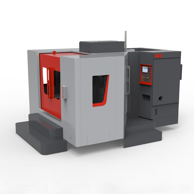
An automatic cutting horizontal machining center is a highly automated CNC machining equipment designed for efficient and precise metal cutting....
An automatic cutting horizontal machining center is a highly automated CNC machining equipment designed for efficient and precise metal cutting. The following is a detailed introduction to the automatic cutting horizontal machining center:
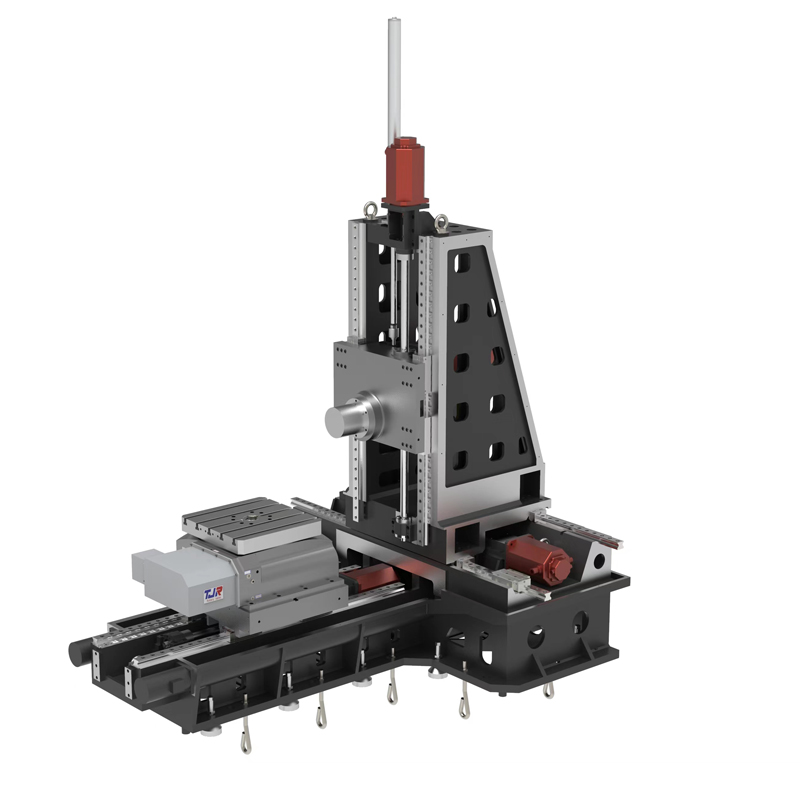
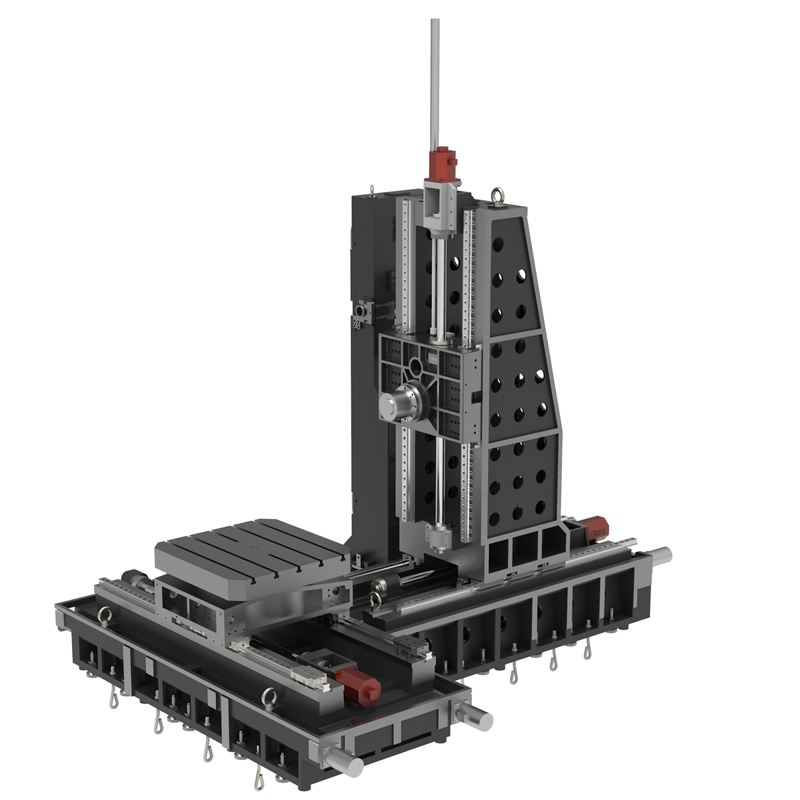
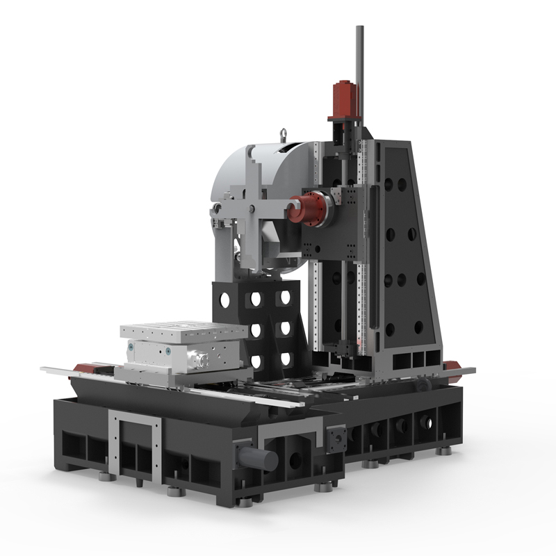
1. Structure and composition
The automatic cutting horizontal machining center is mainly composed of key components such as the machine tool body, spindle box, workbench, tool magazine and control system. The main body of the automatic cutting horizontal machining center is the supporting structure of the entire equipment, including the fuselage, columns and beams, etc., which together ensure the stability and rigidity of the equipment. The main spindle box of the automatic cutting horizontal machining center is the core component, which drives the tool to rotate at high speed to achieve cutting processing. The automatic cutting horizontal machining center table is used to clamp the workpiece and can move in multiple axes to meet complex machining process requirements. The automatic cutting horizontal machining center tool magazine is responsible for storing and automatically replacing tools, and automatically selecting appropriate tools according to processing needs. The control system is the "brain" of the entire equipment, responsible for precise control and guidance of the processing process.
2. Processing process and characteristics
The machining process of the automatic cutting horizontal machining center is highly automated. Through preset programs, the equipment can automatically complete tasks such as workpiece clamping, tool selection and replacement, cutting parameter adjustment, and machining process monitoring. During the machining process of the automatic cutting horizontal machining center, the tool rotates at high speed driven by the spindle, and at the same time, the workbench drives the workpiece to perform feed motion, thereby achieving precise cutting.
Automatic cutting horizontal machining centers have many distinguishing features. First of all, automatic cutting horizontal machining centers are highly flexible and adaptable and can process workpieces of various complex shapes. Secondly, the automatic cutting horizontal machining center adopts advanced CNC technology and automation technology, and the processing accuracy and efficiency of the equipment have been significantly improved. In addition, the automatic cutting horizontal machining center also has good stability and reliability, and can work continuously for a long time, creating more value for the enterprise.
3. Application fields
Automatic cutting horizontal machining centers have been widely used in aerospace, automobile manufacturing, precision machinery and other fields. In the aerospace field, automatic cutting horizontal machining centers are used to process high-precision aerospace parts, such as engine blades, casings, etc. In the field of automobile manufacturing, automatic cutting horizontal machining centers are used to process key components such as engine blocks and crankshafts. In addition, in the field of precision machinery, automatic cutting horizontal machining centers also play an important role and are used to manufacture various high-precision and high-complexity mechanical parts.
In short, the automatic cutting horizontal machining center is an efficient and precise metal processing equipment with wide application prospects and development potential. With the continuous advancement of technology and the continuous expansion of application fields, it will play an even more important role in the future.
| Specifications/model | Unit | WH50A | WH50B | WH63A | WH63B | WH75A | WH75B | WH80A | WH80B | WH100A | WH100B |
| Work content | |||||||||||
| Work surface size (optional) | MM | 500×500 | 500×500 | 630×630 | 630×630 | 750×750 | 750×750 | 800×800 | 800×800 | 1000×1000 | 1000×1000 |
| Workbench indexing (standard) | °C | 0.001 | 0.001 | 1 | 1 | 1 | 1 | 1 | 1 | 1 | 1 |
| Customized workbench (optional) | °C | 1/5/90 | 1/5/90 | 0.001/5/90 | 0.001/5/90 | 0.001/5/90 | 0.001/5/90 | 0.001/5/90 | 0.001/5/90 | 0.001/5/90 | 0.001/5/90 |
| Maximum rotation diameter of worktable | MM | 700 | 700 | 1300 | 1300 | 1400 | 1400 | 1600 | 1600 | 1900 | 1900 |
| X-axis travel | MM | 700 | 700 | 1050 | 1050 | 1300 | 1300 | 1300 | 1300 | 1600 | 1600 |
| Y-axis travel (headstock moves up and down) | MM | 600 | 600 | 770 | 770 | 1000 | 1000 | 1000 | 1000 | 1200 | 1200 |
| Z-axis travel | MM | 600 | 600 | 900 | 900 | 950 | 950 | 1000 | 1000 | 1200 | 1200 |
| Distance from spindle center to worktable | MM | 110-190 | 110-190 | 120-890 | 120-890 | 120-1120 | 120-1120 | 120-1120 | 120-1120 | 120-1320 | 120-1320 |
| Distance from spindle end face to worktable center | MM | 200-800 | 200-800 | 170-1070 | 170-1070 | 250-1200 | 250-1200 | 300-1300 | 300-1300 | 400-1600 | 400-1600 |
| Workbench (slot width*number of slots) | MM | 3-14 | 3-14 | 5-22 | 5-22 | 5-22 | 5-22 | 9-24 | 9-24 | 9-24 | 9-24 |
| Threaded hole (optional) | MM | 24-M14 | 24-M14 | 24-M16 | 24-M16 | 24-M16 | 24-M16 | 24-M16 | 24-M16 | 24-M16 | 24-M16 |
| Workbench load-bearing capacity (per block) | KG | 600 | 600 | 1200 | 1200 | 1700 | 1700 | 2100 | 2100 | 3200 | 3200 |
| Spindle and spindle box specifications | |||||||||||
| Spindle taper hole | ISO | BT50-150 | BT50-150 | BT50-190 | BT50-190 | BT50-190 | BT50-190 | BT50-190 | BT50-190 | BT50-190 | BT50-190 |
| Spindle belt speed (standard/optional) | RPM | 6000 | 6000 | 4000, 6000 | 4000, 6000 | 4000, 6000 | 4000, 6000 | 4000, 6000 | 4000, 6000 | 4000, 6000 | 4000, 6000 |
| Transmission gearbox ratio (optional) | N | / | / | 1:1/1:4 | 1:1/1:4 | 1:1/1:4 | 1:1/1:4 | 1:1/1:4 | 1:1/1:4 | 1:1/1:4 | 1:1/1:4 |
| Electric spindle HSK (optional) | HSK | A63 | A63 | A100 | A100 | A100 | A100 | A100 | A100 | A100 | A100 |
| Electric spindle speed | RPM | 18000 | 18000 | 15000 | 15000 | 15000 | 15000 | 15000 | 15000 | 15000 | 15000 |
| Feeding system | |||||||||||
| Shaft Ball Screw Specifications | MM | 40/40/40 | 40/40/40 | 40/40/50 | 40/40/50 | 50/50/50 | 50/50/50 | 50/50/50 | 50/50/50 | 63/63/63 | 63/63/63 |
| X/Y/Z axis rapid movement speed | M/MIN | 32/24/24 | 32/24/24 | 24/24/20 | 24/24/20 | 24/24/20 | 24/24/20 | 24/24/20 | 24/24/20 | 16/16/12 | 16/16/12 |
| B-axis rapid movement speed | M/MIN | B:15 | B:15 | B:10 | B:10 | B:10 | B:10 | B:10 | B:10 | B:10 | B:10 |
| X/Y/Z axis rail specifications | MM | Roller 45/45/45 | Roller 45/45/45 | Roller 55/55/55 | Roller 55/55/55 | Roller 55/55/55 | Roller 55/55/55 | Roller 55/55/55 | Roller 55/55/55 | Roller 55/55/55 | Roller 55/55/55 |
| Motor connection method | / | Direct | Direct | Direct | Direct | Direct | Direct | Direct | Direct | Direct | Direct |
| Main motor parameters | KW | 11 | 11 | 18.5 | 18.5 | twenty two | twenty two | twenty two | twenty two | twenty two | twenty two |
| X/Y/Z axis motor power | NM | 22/22/22B | 22/22/22B | 30/40/30B | 30/40/30B | 30/40/30B | 30/40/30B | 40/40/30B | 40/40/30B | 40/40/30B | 40/40/30B |
| B-axis motor power | NM | B:8 | B:8 | B:12 | B:12 | B:22 | B:22 | B:22 | B:22 | B:30 | B:30 |
| Axis positioning accuracy | MM | 0.01 | 0.01 | 0.012 | 0.012 | 0.012 | 0.012 | 0.013 | 0.013 | 0.015 | 0.015 |
| Axis item repeat positioning accuracy | MM | 0.005 | 0.005 | 0.005 | 0.005 | 0.005 | 0.005 | 0.006 | 0.006 | 0.006 | 0.006 |
| BPositioning accuracy | SEC | 10" | 10" | 10" | 10" | 10" | 10" | 10" | 10" | 10" | 10" |
| B Repeat positioning accuracy | SEC | 3" | 3" | 3" | 3" | 3" | 3" | 3" | 3" | 3" | 3" |
| Minimum move value | MM | 0.001 | 0.001 | 0.001 | 0.001 | 0.001 | 0.001 | 0.001 | 0.001 | 0.001 | 0.001 |
| Oil and gas pressure system | |||||||||||
| air pressure | KG/MM | 6.5 | 6.5 | 6.5 | 6.5 | 6.5 | 6.5 | 6.5 | 6.5 | 6.5 | 6.5 |
| coolant capacity | L | 450 | 450 | 550 | 550 | 600 | 600 | 650 | 650 | 750 | 750 |
| Lubricating oil capacity L | L | 4 | 4 | 4 | 4 | 4 | 4 | 4 | 4 | 4 | 4 |
| Total power capacity | KVA | 35 | 37 | 40 | 42 | 45 | 47 | 45 | 47 | 45 | 45 |
| Toolholder/Tool Magazine System (specify when ordering) | |||||||||||
| Tool magazine structure | / | Disc knife arm type | Disc knife arm type | Disc knife arm type | Disc knife arm type | Disc knife arm type | Disc knife arm type | Disc knife arm type | Disc knife arm type | Disc knife arm type | Disc knife arm type |
| Number of tool magazines (optional) | T | 24, 32, 40 | 24, 32, 40 | 24, 32, 40 | 24, 32, 40 | 24, 32, 40 | 24, 32, 40 | 24, 32, 40 | 24, 32, 40 | 24, 32, 40 | 24, 32, 40 |
| Knife inventory structure (optional) | / | Chain plate type | Chain plate type | Chain plate type | Chain plate type | Chain plate type | Chain plate type | Chain plate type | Chain plate type | Chain plate type | Chain plate type |
| Number of tool magazines | T | 40/50/60/80 | 40/50/60/80 | 40/50/60/80 | 40/50/60/80 | 40/50/60/80 | 40/50/60/80 | 40/50/60/80 | 40/50/60/80 | 40/50/60/80 | 40/50/60/80 |
| Tool changing time T | SEC | 3.8/5.2 | 3.8/5.2 | 3.8/5.2 | 3.8/5.2 | 3.8/5.2 | 3.8/5.2 | 3.8/5.2 | 3.8/5.2 | 3.8/5.2 | 3.8/5.2 |
| Maximum tool weight (optional) KGS | 8/10 | 8/10 | 15/18 | 15/18 | 15/18 | 15/18 | 15/18 | 15/18 | 15/18 | 15/18 | 15/18 |
| Maximum tool/adjacent tool clearance diameter | MM | φ110/φ200 | φ110/φ200 | φ110/φ200 | φ110/φ200 | φ110/φ200 | φ110/φ200 | φ110/φ200 | φ110/φ200 | φ110/φ200 | φ110/φ200 |
| Form factor | |||||||||||
| Weight approx. | KG | 5.5 | 6.5 | 12.5 | 15.5 | 14 | 17 | 18.5 | 22.5 | 19.5 | 19.5 |
| Machine length | MM | 3500 | 4800 | 4800 | 6100 | 5100 | 7000 | 5350 | 7200 | 5300 | 5300 |
| Machine width | MM | 3100 | 3300 | 3400 | 4150 | 4200 | 5500 | 4200 | 5680 | 4500 | 4500 |
| Machine height (maximum) | MM | 3200 | 3200 | 3400 | 4550 | 4400 | 4400 | 4400 | 4400 | 4700 | 4700 |
| Machine tool structure | / | Positive T shape | Positive T shape | Inverted T shape | Inverted T shape | Inverted T shape | Inverted T shape | Inverted T shape | Inverted T shape | Inverted T shape | Inverted T shape |
| Chip removal method | / | Twin screw rear row | Twin screw rear row | Twin screw single chain plate | Twin screw single chain plate | Twin screw single chain plate | Twin screw single chain plate | Twin screw single chain plate | Twin screw single chain plate | Twin screw single chain plate | Twin screw single chain plate |

 English
 日本語
日本語 한국어
한국어 Россия
  Français
 España
 عرب .
عرب .  Português
 Deutsch
 भारत
भारत Нидерланды
