- contact us
- Sales Manager:
Asia Li - Email:
asia.cncmachine@gmail.com - Wechat ID:
Asia-Li_90727( +8613210773378) TEL:+8613210773378 - TEL:
8613210773378 - Whatsapp:
8613210773378
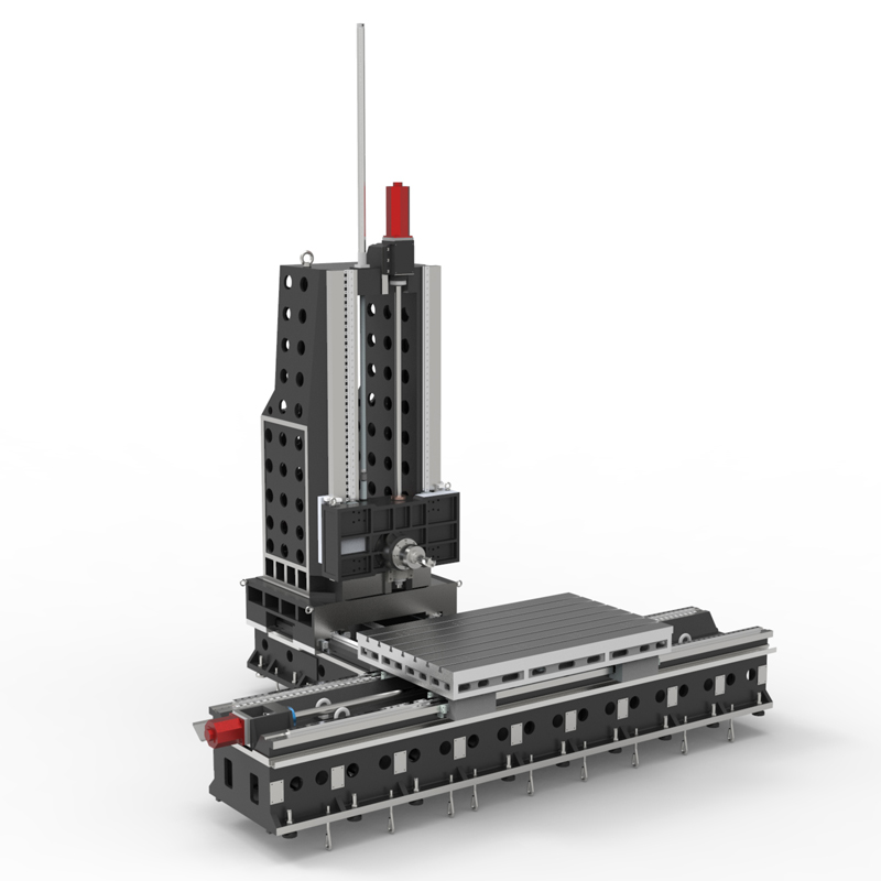

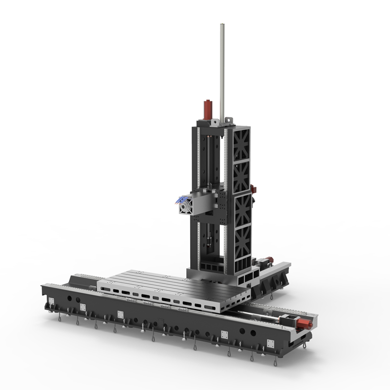
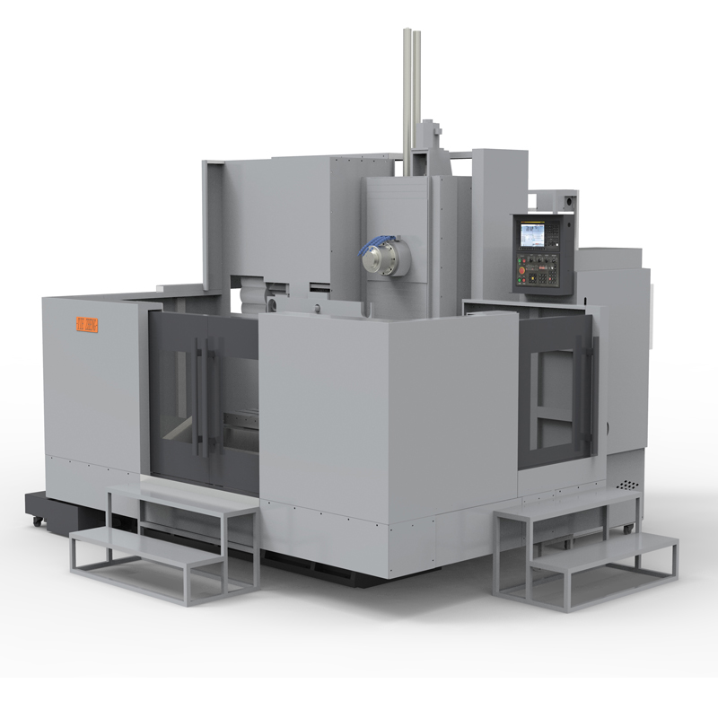
Fully automatic horizontal machining center
The fully automatic horizontal machining center is an efficient CNC machine tool with the following features and advantages:...
The fully automatic horizontal machining center is an efficient CNC machine tool with the following features and advantages:
1. Horizontal structure: The spindle of the machining center is placed horizontally, and the workpiece is fixed on the workbench, which is beneficial to the stable processing of heavy workpieces, and facilitates the outflow and cleaning of cutting fluid, improving processing efficiency and quality.
2. Full automation: The fully automatic horizontal machining center adopts a fully automated processing process, including automatic tool changing, automatic workpiece clamping, automatic feeding and other functions, which reduces manual intervention and improves production efficiency and consistency.
3. Multi-axis control: The fully automatic horizontal machining center is equipped with a multi-axis CNC system, which can realize multi-axis linkage control, including three-axis, four-axis or even more axial motion control, making the processing of complex workpieces more accurate and efficient.
4. High speed and high precision: The main spindle of the fully automatic horizontal machining center adopts a high-speed electric spindle, combined with a precise CNC system, to achieve high-speed and high-precision processing, and is suitable for demanding precision machining fields.
5. Flexible and multi-functional: Fully automatic horizontal machining centers are usually equipped with a variety of processing tools and functional modules, which can realize a variety of processing operations, including milling, drilling, tapping, boring, etc., and can flexibly adapt to the processing needs of different workpieces.
6. High efficiency and energy saving: The fully automatic horizontal machining center adopts advanced processing technology and energy-saving design, such as high-efficiency spindle, intelligent energy-saving control system, etc., which not only improves processing efficiency, but also reduces energy consumption, and meets the requirements of sustainable development. .
7. Friendly human-computer interaction: The fully automatic horizontal machining center is equipped with an intuitive human-machine interface and operating system, which is simple to operate and easy to master. The operator can quickly adjust parameters and monitor the processing process.
8. Data management: The fully automatic horizontal machining center has data collection, monitoring and analysis functions, which can realize data management of the production process and improve the level of production management and production quality.
Fully automatic horizontal machining center is widely used in aerospace, automobile manufacturing, mold processing, shipbuilding and other fields. It is an efficient and precise CNC processing equipment.
| Specifications/Models | Unit | WY10 | WY15 | WY20 | WY25 | WY30 | WY40 |
| Work content | |||||||
| Work surface size | MM | 1200×1600 | 1700×800 | 2000×1200 | 2500×1400 | 3000×1400 | 4000×1400 |
| X-axis travel | MM | 1100 | 1600 | 2100 | 2600 | 3100 | 4200 |
| Y-axis spindle box up and down travel (standard/optional) | MM | 700/900 | 700/900 | 1000/1500 | 1000/1500 | 1500/2000 | 1500/2000 |
| Z-axis column front and rear travel (standard, optional) | MM | 800 | 800/1200 | 800/1200 | 800/1200 | 800/1200 | 800/1200 |
| Distance from spindle center to worktable | MM | 120-890 | 120-1120 | 120-1320 | 120-1820 | 120-1820 | 120-2120 |
| Distance from spindle end face to worktable center | MM | 130-1030 | 200-1200 | 400-1600 | 500-1700 | 500-1700 | 700-1700 |
| Workbench slot width + T slot | MM | 5-22 | 9-28 | 9-28 | 11-28 | 11-28 | 11-28 |
| Workbench load-bearing | KG | 1200 | 2500 | 3000 | 6000 | 10000 | 14000 |
| Spindle and spindle specifications | |||||||
| Spindle taper hole | ISO | BT50-190 | BT50-190 | BT50-190 | BT50-190 | BT50-190 | BT50-190 |
| Spindle speed | RPM | 4000/6000 | 4000/6000 | 4000/6000 | 4000/6000 | 4000/6000 | 4000/6000 |
| Type A boring bar specification diameter (optional) | MM | / | 110 | 110 | 130 | 130 | 130 |
| Boring bar stroke Z1 (optional) | MM | / | 550 | 550 | 550 | 550 | 550 |
| Type B square ram specifications square type (optional) | MM | / | / | 320 | 320 | 320 | 320 |
| Square ram stroke Z2 (optional) | MM | / | / | 600 | 600 | 600 | 600 |
| T-shaped workbench (slot width * number of slots) | / | 28*300 | / | 28*300 | 28*300 | 28*300 | 28*300 |
| Feeding system | |||||||
| Shaft Ball Screw Specifications | MM | 40/40/50 | 50/50/50 | 63/50/50 | 63/50/50 | 63/50/50 | 80/63/63 |
| XYZ axis rapid movement speed | M/MIN | 32.32.32 | 32.32.32 | 24.24.24 | 24.24.24 | 20.24.24 | 20.24.24 |
| X/Z axis wire gauge specifications | MM | Roller 55/55 | Roller 55/55 | Roller 55/55 | Roller 55/55 | Roller 55/55 | Roller 55/55 |
| Y-axis wire gauge specifications | MM | Roller 55 | Roller 55 | Roller 45*4 | Roller 45*4 | Roller 45*4 | Roller 45*4 |
| Motor connection method | / | Direct | Direct | Direct connection + reducer | Direct connection + reducer | Direct connection + reducer | Direct connection + reducer |
| Main motor parameter marking/selection | KW | 22/+reducer | 22/+reducer | 22/+reducer | 22/+reducer | 22/+reducer | 22/+reducer |
| Axis positioning accuracy | MM | ±0.005 | ±0.005 | ±0.005 | ±0.005 | ±0.005 | ±0.005 |
| Axis item repeat positioning accuracy | MM | ±0.003 | ±0.003 | ±0.003 | ±0.003 | ±0.003 | ±0.003 |
| Minimum move value | MM | 0.001 | 0.001 | 0.001 | 0.001 | 0.001 | 0.001 |
| Oil and gas pressure system | |||||||
| Spindle box balancing system (vertical installation) | / | gas balance | gas balance | gas balance | gas balance | gas balance | gas balance |
| air pressure | KG/MM | 6.5 | 6.5 | 6.5 | 6.5 | 6.5 | 6.5 |
| coolant capacity | L | 550 | 550 | 550 | 550 | 550 | 550 |
| Lubricating oil capacity L | L | 4 | 4 | 4 | 4 | 4 | 4 |
| Toolholder/Tool Magazine System (specify when ordering) | |||||||
| Tool magazine structure | / | Disc knife arm type | Disc knife arm type | Disc knife arm type | Disc knife arm type | Disc knife arm type | Disc knife arm type |
| Number of tool magazines (optional) | T | 24/32 | 24/32 | 24/32 | 24/32 | 24/32 | 24/32 |
| Knife inventory structure (optional) | / | Chain plate type tool magazine | Chain plate type tool magazine | Chain plate type tool magazine | Chain plate type tool magazine | Chain plate type tool magazine | Chain plate type tool magazine |
| Number of tool magazines | T | 40/50/60/80 | 40/50/60/80 | 40/50/60/80 | 40/50/60/80 | 40/50/60/80 | 40/50/60/80 |
| Tool changing time | MM | 5.2 | 5.2 | 5.2 | 5.2 | 5.2 | 5.2 |
| Maximum tool weight | KGS | 18 | 18 | 18 | 18 | 18 | 18 |
| Form factor | |||||||
| Weight approx. | T | 9 | 13/15 | 16/18 | 22/24 | 24/26 | 32/34 |
| Machine width | MM | 3000 | 4000 | 5000 | 6500 | 7500 | 9700 |
| Machine length | MM | 4500 | 5500 | 5800 | 6300 | 6300 | 7300 |
| Machine height (maximum) | MM | 4100 | 4300 | 5000 | 5500 | 5500 | 6000 |
| Machine tool mechanism | / | Inverted T shape | Inverted T shape | Inverted T shape | Inverted T shape | Inverted T shape | Inverted T shape |
| Chip removal method | / | Twin screw + chain plate | Twin screw + chain plate | Twin screw + chain plate | Twin screw + chain plate | Twin screw + chain plate | Twin screw + chain plate |

 English
 日本語
日本語 한국어
한국어 Россия
  Français
 España
 عرب .
عرب .  Português
 Deutsch
 भारत
भारत Нидерланды
