- contact us
- Sales Manager:
Asia Li - Email:
asia.cncmachine@gmail.com - Wechat ID:
Asia-Li_90727( +8613210773378) TEL:+8613210773378 - TEL:
8613210773378 - Whatsapp:
8613210773378
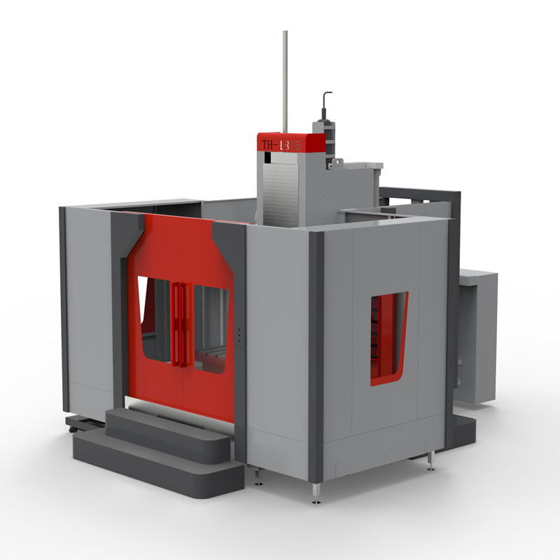
Heavy cutting horizontal machining center
The heavy cutting horizontal machining center is a machine tool equipment specially used for heavy cutting....
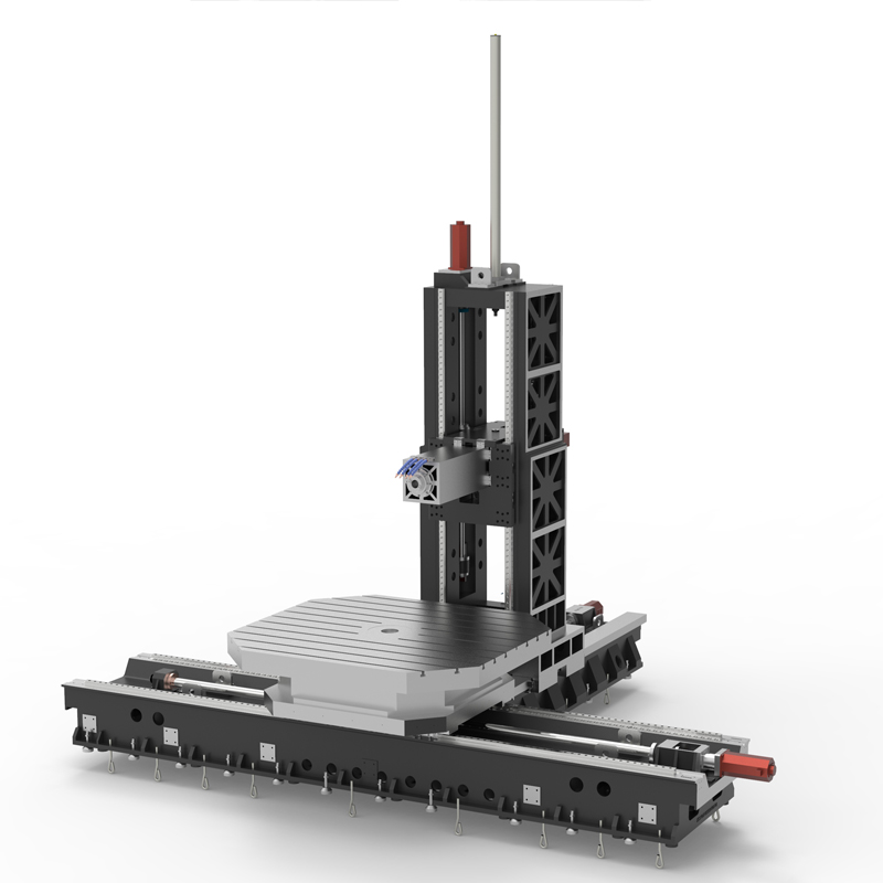
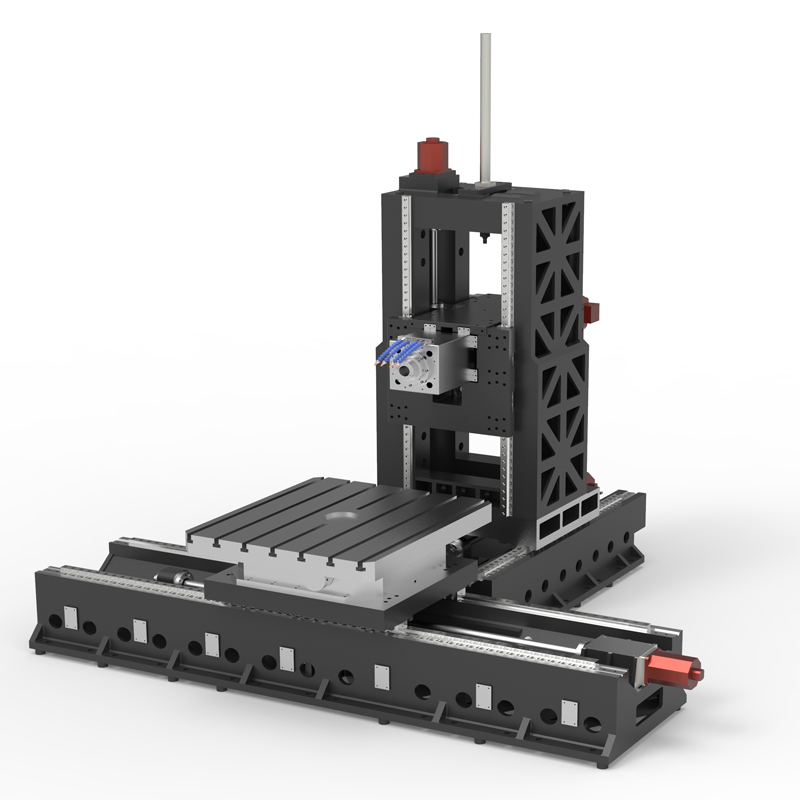
The heavy cutting horizontal machining center is a machine tool equipment specially used for heavy cutting. It inherits the basic characteristics of horizontal machining centers and is optimized and improved for heavy cutting tasks. Here are some key features and application areas for heavy cutting horizontal machining centers:
1. Structural characteristics:
Heavy-cutting horizontal machining centers typically have more robust and stable structures to withstand the high impact forces and vibrations generated during heavy cutting.
Heavy-cutting horizontal machining centers may be equipped with higher-power spindles and drive systems to provide higher cutting forces and torques to meet the needs of heavy-duty cutting.
The heavy cutting horizontal machining center table and fixture system are also specially designed to ensure that the workpiece can be firmly clamped during heavy cutting and prevent the workpiece from moving or deforming.
2. Tool magazine and tools:
Heavy-cutting horizontal machining centers may have larger tool magazine capacities to accommodate different cutting tasks and tool needs.
For heavy cutting horizontal machining center tools, specially designed tools may be used to cope with the high cutting forces and high temperatures during heavy cutting.
3. Cooling and lubrication system:
Heavy-cutting horizontal machining center Since heavy cutting generates a lot of heat, the cooling and lubrication system is particularly important in heavy-cutting horizontal machining centers. An efficient cooling system can ensure stable operation of machine tools and extend their service life.
A proper lubrication system for horizontal machining centers helps reduce friction and wear and improve cutting efficiency.
4.Application fields:
Heavy-cutting horizontal machining centers are widely used in processing fields that require large cutting forces, high cutting efficiency and high precision, such as aerospace, energy, heavy industry and other fields.
In the aerospace field, heavy-cutting horizontal machining centers are often used to process large structural parts and engine components; in the energy field, heavy-cutting horizontal machining centers can be used to process parts of large equipment; in the heavy industry field, heavy-cutting horizontal machining centers It can be used to process large machinery and equipment and the manufacturing of heavy parts.
It should be noted that when using a heavy-cutting horizontal machining center, special attention needs to be paid to the selection of cutting parameters and the monitoring of the cutting process to ensure processing quality and the safety of the machine tool. In addition, heavy-cutting horizontal machining center operators should have extensive experience and skills to fully utilize the performance and advantages of the machine tool.
In general, the heavy-cutting horizontal machining center is an efficient and stable processing equipment that can meet the needs of heavy-cutting processing and plays an important role in many fields.
| Specifications/model | Unit | WB14B/C/D | WB18B/C/D | WB24B/C/D |
| Workbench specifications | ||||
| Rotary work surface dimensions | MM | 1400×1200 | 1800×1600 | 2400×2200 |
| Turntable structure (standard) | °C | 0.001 | 0.001 | 0.001 |
| Turntable structure (optional) | °C | 1/5/90 | 1/5/90 | 1/5/90 |
| Turntable load-bearing | T | 7 | 12 | 20 |
| Machine tool mechanism | / | Inverted T shape | Inverted T shape | Inverted T shape |
| Worktable left and right travel X mark/select | MM | 2000/2500 | 2500/3000 | 3000/4000 |
| Spindle box upper and lower stroke Y mark/select MM | 1000/1500 | 1500/2000 | 2000/2500 | |
| Column front and rear travel Z1 | MM | 1000 | 1000 | 1500 |
| Type B square ram front and rear travel Z2 | MM | 600 | 600 | 600 |
| Square ram specifications | MM | 360*360 | 360*360 | 360*360 |
| Maximum spindle speed/optional | RPM | 4000/6000 | 4000/6000 | 4000/6000 |
| C type boring bar front and rear travel Z2 | MM | 600 | 600 | 600 |
| Boring bar specifications | MM | 130 | 130 | 130 |
| Maximum spindle speed/optional | RPM | 1200/2000 | 1200/2000 | 1200/2000 |
| Distance from spindle end face to table center | MM | 200-1400 | 500-1700 | 600-2300 |
| Distance from spindle center to table surface | MM | 100-11/160000 | 100-1600/2100 | 100-2100/2600 |
| Workbench T-slot (slot width * number of slots) | / | 24*7 | 24*9 | 24*11 |
| Spindle content | ||||
| Spindle model/installation dimensions | MM | BT50/190 | BT50/190 | BT50/190 |
| Spindle motor | KW | 22KW | 22KW | 22KW |
| Maximum spindle speed/optional | RPM | 3000/4000 | 3000/4000 | 3000/4000 |
| Spindle drive | / | Variable speed gear transmission | Variable speed gear transmission | Variable speed gear transmission |
| Axis item content | ||||
| X-axis guide rail specifications/quantity | MM/N | Roller 55/2 | Roller 55/2 | Roller 55/2 |
| Y-axis guide rail specifications/quantity | MM/N | Roller 45/4 | Roller 45/4 | Roller 45/4 |
| Z-axis guide rail specifications/quantity | MM/N | Roller 55/2+hard rail | Roller 55/2+hard rail | Roller 55/2+hard rail |
| Three-axis ball screw specifications | MM | 63, 50, 63 | 63, 50, 63 | 63, 50, 63 |
| Square ram or boring bar ball screw specifications | MM | 40 | 40 | 40 |
| XY fast movement speed | M/MIN | 12, 12 | 12, 12 | 12, 12 |
| Z1/Z2 speed moving speed | M/MIN | 12, 20 | 12, 20 | 12, 20 |
| Three-axis motor connection method | / | direct connection | Reducer + direct connection | Reducer + direct connection |
| X, Y brake power | NM | 40, 40B | 40, 40B | 40, 40B |
| Z1, Z2 power | NM | 40, 22 | 40, 22 | 40, 22 |
| Spindle box balancing system | / | Nitrogen balance | Nitrogen balance | Nitrogen balance |
| air pressure | KG/MM | 6.5 | 6.5 | 6.5 |
| coolant capacity | L | 450 | 450 | 450 |
| Lubricating oil capacity | L | 4 | 4 | 4 |
| Oil and gas pressure system | ||||
| battery capacity | KW | 55 | 55 | 55 |
| Voltage floating | VAC | 380±5% | 380±5% | 380±5% |
| Phase | PHASE | 3 boxes 5 lines | 3 boxes 5 lines | 3 boxes 5 lines |
| air pressure | KG | 6.5-8 | 6.5-8 | 6.5-8 |
| Form factor | ||||
| Machine weight (approx.) | T | 22/26 | 26/30 | 33/37 |
| Machine length (front and rear) markings | MM | 4000 | 4500 | 5000 |
| Machine width (left and right) mark | MM | 6000 | 7000 | 8000 |
| Machine height (maximum) mark | MM | 4500 | 4500 | 4500 |
| Chip removal method | / | Twin screw/chain plate type | Twin screw/chain plate type | Twin screw/chain plate type |

 English
 日本語
日本語 한국어
한국어 Россия
  Français
 España
 عرب .
عرب .  Português
 Deutsch
 भारत
भारत Нидерланды
