- contact us
- Sales Manager:
Asia Li - Email:
asia.cncmachine@gmail.com - Wechat ID:
Asia-Li_90727( +8613210773378) TEL:+8613210773378 - TEL:
8613210773378 - Whatsapp:
8613210773378
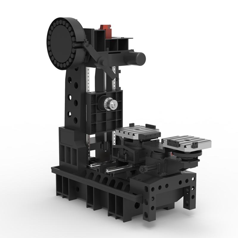
Horizontal cross structure machining center
The horizontal cross structure machining center is a kind of machine tool equipment. Its spindle is arranged horizontally with the work table. After the workpiece is clamped at one time, the processing of the remaining four surfaces except the mounting surface and top surface can be completed....
The horizontal cross structure machining center is a kind of machine tool equipment. Its spindle is arranged horizontally with the work table. After the workpiece is clamped at one time, the processing of the remaining four surfaces except the mounting surface and top surface can be completed.
The working principle of the horizontal cross structure machining center mainly relies on the rotation of the spindle, the movement of the workbench, the selection of tools and the cutting process, as well as the application of coolant. The rotation of the spindle of the horizontal cross structure machining center drives the cutting tool to perform cutting. The movement of the workbench controls the relative position and cutting path of the workpiece and the cutting tool. The selection of the cutting tool and the cutting process are determined according to the workpiece material and processing requirements. At the same time, the application of coolant in horizontal cross structure machining centers helps reduce temperature, extend tool service life, clean the cutting area, and ensure processing quality.
Horizontal cross structure machining centers are widely used in aerospace, medical equipment, energy, transportation, machinery and other fields. For example, in the aerospace field, horizontal cross structure machining centers can be used to produce high-precision aerospace parts; in the field of medical equipment, horizontal cross structure machining centers can produce high-precision medical equipment parts; in the energy field, horizontal cross structure machining centers can be used to produce high-precision aerospace parts. Structural machining centers can be used to manufacture high-precision parts for nuclear power plants; in the transportation field, horizontal cross structural machining centers can be used to manufacture high-strength parts for high-speed rail and subway; in the mechanical field, horizontal cross structural machining centers can be used to manufacture various complex-shaped mechanical parts.
In general, the horizontal cross structure machining center is an important piece of equipment in modern manufacturing. It has the characteristics of high precision, high efficiency and high stability, and plays a vital role in improving processing efficiency and workpiece quality.
| Specifications/model | Unit | WA50 | WA63 | WA80 |
| Work content | ||||
| Installation turntable specifications (optional) | MM | 500*500 | 630*630 | 800*800 |
| Workbench indexing (standard) | N | 1 degree 1 minute | 1 degree 1 minute | 1 degree 1 minute |
| Customized workbench (optional) | N | Customize other graduations | Customize other graduations | Customize other graduations |
| Maximum rotation diameter of worktable | MM | 850 | 1150 | 1300 |
| X-axis travel | MM | 800 | 1100 | 1300 |
| Y-axis travel (headstock moves up and down) | MM | 550 | 750 | 900 |
| Z-axis travel | MM | 500 | 600 | 700 |
| Distance from spindle center to worktable | MM | 110-660 | 110-860 | 110-1010 |
| Distance from spindle end face to worktable center | MM | 250-650 | 210-710 | 300-900 |
| Workbench (slot width*number of slots) | MM | 3-14 | 5-14 | 5-14 |
| Threaded hole (optional) | MM | 24-M14 | 24-M14 | 24-M14 |
| Workbench load-bearing | KG | 600 | 800 | 1000 |
| Spindle and spindle box specifications | ||||
| Spindle taper hole | ISO | BT40-150 | BT50-150 | BT50-190 |
| Spindle speed | RPM | 8000 | 8000 | 8000 |
| Feeding system | ||||
| Shaft Ball Screw Specifications | MM | 40/40/40 | 40/40/40 | 40/40/40 |
| X-axis rapid movement speed | M/MIN | X:48 | X:32 | X:32 |
| Y-axis rapid movement speed | M/MIN | Y:48 | Y:32 | Y:32 |
| Z-axis rapid movement speed | M/MIN | Z:48 | Z:32 | Z:32 |
| X/Y/Z axis rail specifications | MM | Roller 35/45/45 | Roller 45/45/45 | Roller 45/45/45 |
| Motor connection method | / | Direct | Direct | Direct |
| Main motor parameters | KW | 11 | 11 | 15 |
| X-axis motor power | NM | X:22 | X:22 | X:22 |
| Y-axis motor power | NM | Y:22B | Y:22B | Y:22B |
| Z-axis motor power | NM | Z:22 | Z:22 | Z;30 |
| B-axis motor power | NM | B:8 | B:12 | B:12 |
| Axis positioning accuracy | MM | ±0.005 | ±0.005 | ±0.005 |
| Axis item repeat positioning accuracy | MM | ±0.003 | ±0.003 | ±0.003 |
| BPositioning accuracy | MM | 10" | 10" | 10" |
| B Repeat positioning accuracy | MM | 5" | 5" | 5" |
| Minimum move value | MM | 0.001 | 0.001 | 0.001 |
| Oil and gas pressure system | ||||
| air pressure | KG/MM | 6.5 | 6.5 | 6.5 |
| coolant capacity | L | 450 | 450 | 450 |
| Lubricating oil capacity L | L | 4 | 4 | 4 |
| Toolholder/Tool Magazine System (specify when ordering) | ||||
| Tool magazine structure | / | Top disc type | Top disc type | Top disc type |
| Number of tool magazines (optional) | T | twenty four | twenty four | twenty four |
| Tool changing time | MM | 3.2 | 3.2 | 3.2 |
| Maximum tool weight | KGS | 12 | 15 | 15 |
| Form factor | ||||
| Weight approx. | KG | 6.5 | 8.5 | 10 |
| Machine length | MM | 3500 | 3800 | 4000 |
| Machine width | MM | 2500 | 3000 | 3500 |
| Machine width (height) | MM | 2800 | 3000 | 3300 |
| Machine height (minimum) | MM | 2300 | 2500 | 2900 |
| Machine tool structure | / | Cross type | Cross type | Cross type |
| Chip removal method | / | back row | back row | back row |

 English
 日本語
日本語 한국어
한국어 Россия
  Français
 España
 عرب .
عرب .  Português
 Deutsch
 भारत
भारत Нидерланды
