- contact us
- Sales Manager:
Asia Li - Email:
asia.cncmachine@gmail.com - Wechat ID:
Asia-Li_90727( +8613210773378) TEL:+8613210773378 - TEL:
8613210773378 - Whatsapp:
8613210773378
Horizontal machining center milling metal
Horizontal machining centers excel at milling metal, mainly due to their unique design and functional features....
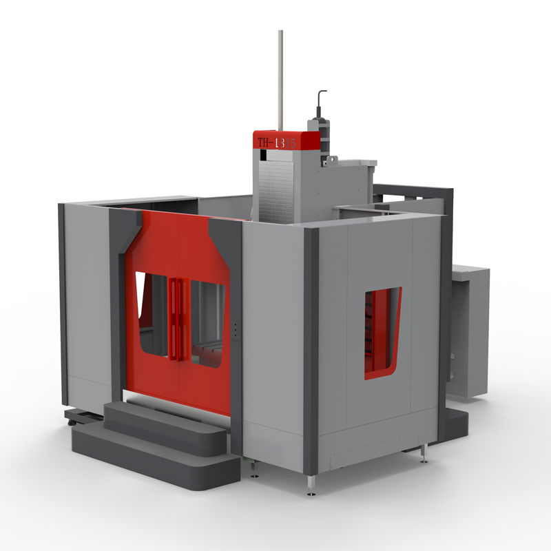
Horizontal machining centers excel at milling metal, mainly due to their unique design and functional features. This kind of machine tool equipment is specially designed for high-precision and high-efficiency metal cutting processing, and can handle a variety of complex metal processing tasks.
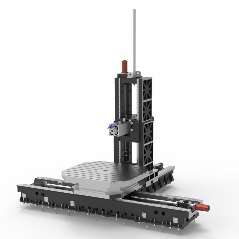
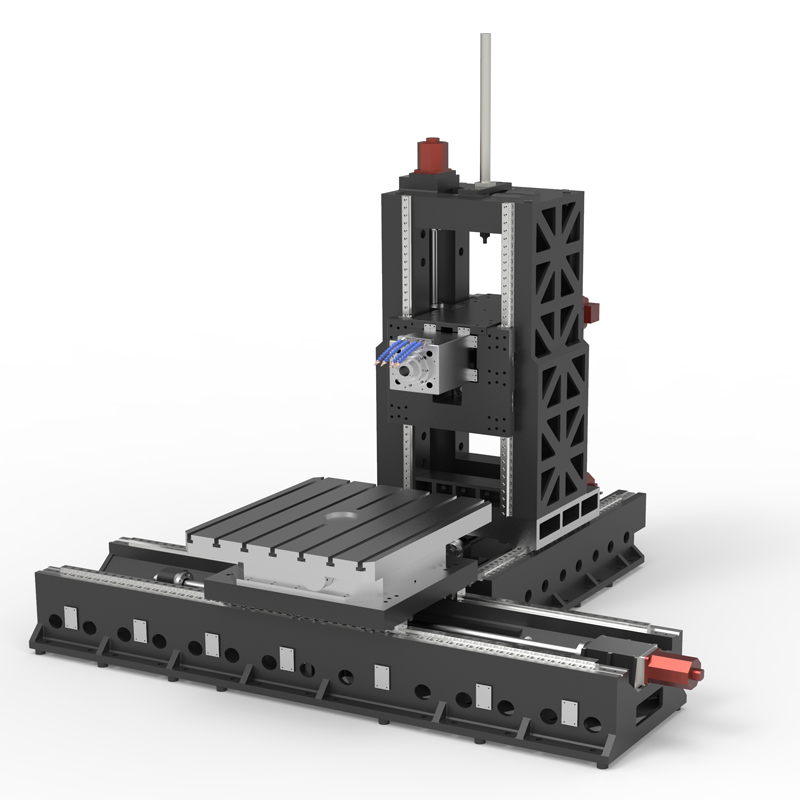
First of all, the horizontal machining center adopts a horizontal layout with the spindle parallel to the worktable, which makes it more stable when processing large or heavy workpieces. At the same time, the solid base and column structure of the horizontal machining center ensures the rigidity and accuracy of the horizontal machining center during the machining process, effectively reducing machining errors caused by vibration or deformation.
Secondly, horizontal machining centers have multi-axis machining capabilities and are usually equipped with multiple coordinate axes and rotary axes (or rotary tables) to achieve complex three-dimensional machining tasks. This allows the horizontal machining center to easily cope with the various cutting angles and depth changes involved in the metal milling process, ensuring machining accuracy and surface quality.
In addition, horizontal machining centers are also equipped with advanced CNC systems and automation functions, such as automatic tool change, automatic measurement and automatic compensation. These functions not only improve processing efficiency and reduce the labor intensity of operators, but also ensure the stability and reliability of the processing process.
In terms of metal milling, horizontal machining centers can complete various complex milling processes, including plane milling, curved surface milling, contour milling, etc. By selecting appropriate tools and cutting parameters, it can achieve fine processing of metal materials and meet the shape and size requirements of various parts.
In addition, horizontal machining centers are also widely used in aerospace, automobile manufacturing, mold manufacturing and other fields, which have extremely high requirements for metal processing accuracy and efficiency. By using a horizontal machining center for metal milling, production efficiency and product quality can be significantly improved, and production costs can be reduced.
It should be noted that when using a horizontal machining center for metal milling, it is necessary to reasonably select tools, cutting parameters and processing sequences to ensure the stability of the processing process and processing quality. At the same time, machine tools also need to be maintained and maintained regularly to ensure their normal operation and extend their service life.
In short, horizontal machining centers perform well in milling metal and have the advantages of high precision, high efficiency, and multi-function. Through the rational application of this kind of machine tool equipment, fine processing of metal materials can be achieved to meet the processing needs of various complex parts.
| Specifications/model | Unit | WB14B/C/D | WB18B/C/D | WB24B/C/D |
| Workbench specifications | ||||
| Rotary work surface dimensions | MM | 1400×1200 | 1800×1600 | 2400×2200 |
| Turntable structure (standard) | °C | 0.001 | 0.001 | 0.001 |
| Turntable structure (optional) | °C | 1/5/90 | 1/5/90 | 1/5/90 |
| Turntable load-bearing | T | 7 | 12 | 20 |
| Machine tool mechanism | / | Inverted T shape | Inverted T shape | Inverted T shape |
| Worktable left and right travel X mark/select | MM | 2000/2500 | 2500/3000 | 3000/4000 |
| Spindle box upper and lower stroke Y mark/select MM | 1000/1500 | 1500/2000 | 2000/2500 | |
| Column front and rear travel Z1 | MM | 1000 | 1000 | 1500 |
| Type B square ram front and rear travel Z2 | MM | 600 | 600 | 600 |
| Square ram specifications | MM | 360*360 | 360*360 | 360*360 |
| Maximum spindle speed/optional | RPM | 4000/6000 | 4000/6000 | 4000/6000 |
| C type boring bar front and rear travel Z2 | MM | 600 | 600 | 600 |
| Boring bar specifications | MM | 130 | 130 | 130 |
| Maximum spindle speed/optional | RPM | 1200/2000 | 1200/2000 | 1200/2000 |
| Distance from spindle end face to table center | MM | 200-1400 | 500-1700 | 600-2300 |
| Distance from spindle center to table surface | MM | 100-11/160000 | 100-1600/2100 | 100-2100/2600 |
| Workbench T-slot (slot width * number of slots) | / | 24*7 | 24*9 | 24*11 |
| Spindle content | ||||
| Spindle model/installation dimensions | MM | BT50/190 | BT50/190 | BT50/190 |
| Spindle motor | KW | 22KW | 22KW | 22KW |
| Maximum spindle speed/optional | RPM | 3000/4000 | 3000/4000 | 3000/4000 |
| Spindle drive | / | Variable speed gear transmission | Variable speed gear transmission | Variable speed gear transmission |
| Axis item content | ||||
| X-axis guide rail specifications/quantity | MM/N | Roller 55/2 | Roller 55/2 | Roller 55/2 |
| Y-axis guide rail specifications/quantity | MM/N | Roller 45/4 | Roller 45/4 | Roller 45/4 |
| Z-axis guide rail specifications/quantity | MM/N | Roller 55/2+hard rail | Roller 55/2+hard rail | Roller 55/2+hard rail |
| Three-axis ball screw specifications | MM | 63, 50, 63 | 63, 50, 63 | 63, 50, 63 |
| Square ram or boring bar ball screw specifications | MM | 40 | 40 | 40 |
| XY fast movement speed | M/MIN | 12, 12 | 12, 12 | 12, 12 |
| Z1/Z2 speed moving speed | M/MIN | 12, 20 | 12, 20 | 12, 20 |
| Three-axis motor connection method | / | direct connection | Reducer + direct connection | Reducer + direct connection |
| X, Y brake power | NM | 40, 40B | 40, 40B | 40, 40B |
| Z1, Z2 power | NM | 40, 22 | 40, 22 | 40, 22 |
| Spindle box balancing system | / | Nitrogen balance | Nitrogen balance | Nitrogen balance |
| air pressure | KG/MM | 6.5 | 6.5 | 6.5 |
| coolant capacity | L | 450 | 450 | 450 |
| Lubricating oil capacity | L | 4 | 4 | 4 |
| Oil and gas pressure system | ||||
| battery capacity | KW | 55 | 55 | 55 |
| Voltage floating | VAC | 380±5% | 380±5% | 380±5% |
| Phase | PHASE | 3 boxes 5 lines | 3 boxes 5 lines | 3 boxes 5 lines |
| air pressure | KG | 6.5-8 | 6.5-8 | 6.5-8 |
| Form factor | ||||
| Machine weight (approx.) | T | 22/26 | 26/30 | 33/37 |
| Machine length (front and rear) markings | MM | 4000 | 4500 | 5000 |
| Machine width (left and right) mark | MM | 6000 | 7000 | 8000 |
| Machine height (maximum) mark | MM | 4500 | 4500 | 4500 |
| Chip removal method | / | Twin screw/chain plate type | Twin screw/chain plate type | Twin screw/chain plate type |

 English
 日本語
日本語 한국어
한국어 Россия
  Français
 España
 عرب .
عرب .  Português
 Deutsch
 भारत
भारत Нидерланды
