- contact us
- Sales Manager:
Asia Li - Email:
asia.cncmachine@gmail.com - Wechat ID:
Asia-Li_90727( +8613210773378) TEL:+8613210773378 - TEL:
8613210773378 - Whatsapp:
8613210773378
CNC gantry machining center
The CNC gantry machining center is a high-precision, high-efficiency mechanical processing equipment that is widely used in aviation, automobiles, molds, semiconductors and other fields....
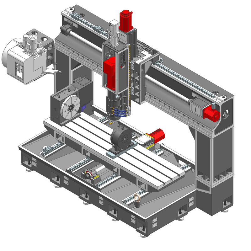
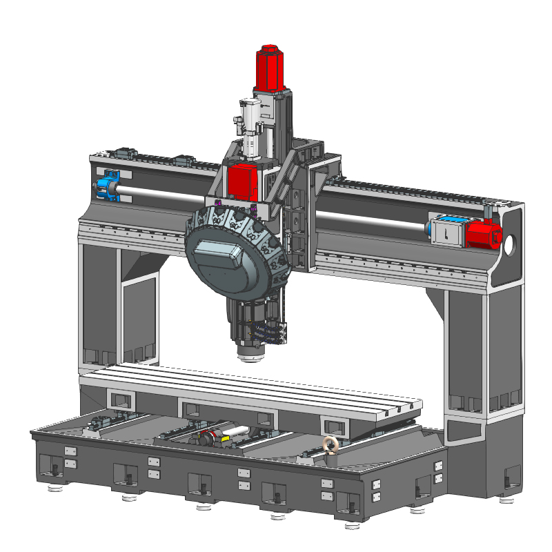
The CNC gantry machining center is a high-precision, high-efficiency mechanical processing equipment that is widely used in aviation, automobiles, molds, semiconductors and other fields. The CNC gantry machining center mainly consists of double columns and a top beam to form a portal structure frame. The axis of the spindle Z axis is set perpendicular to the workbench, so that the equipment can perform linear or curved control in three coordinate directions (X, Y, Z axes). Movement to achieve high-precision machining of complex parts.
In the automobile manufacturing industry, CNC gantry machining centers are used to process body parts, engine parts, chassis components, etc. They can achieve high-precision cutting and processing of complex curved surfaces and improve the quality and accuracy of automobile parts. In the aerospace industry, due to its very high requirements for precision and quality of parts, CNC gantry machining centers can meet these requirements and are widely used in the processing of aircraft structural parts, engine parts, aerospace equipment, etc. CNC gantry machining centers have improved Production efficiency and workpiece quality.
In addition, the working principle of the CNC gantry machining center is to use CAD/CAM software to convert the designed model into G code that can be recognized by the machine tool, and then control each actuator of the machine tool to complete the processing operation. This processing method not only improves processing accuracy, but also greatly improves production efficiency.
In general, the CNC gantry machining center is a powerful and widely used mechanical processing equipment, which is of great significance for improving product quality and production efficiency.
| Specifications/model | unit | SFA/T1512 | SFA/T2012 | SFA/T2016 | SFA/2512T | SFA/T2516 | SFA/T3012 | SFA/T3016 |
| Work content | ||||||||
| Workbench size (X-axis direction) | MM | 1500*1200 | 2000*12000 | 2000*16000 | 2500*1200 | 1500*1600 | 3000*1200 | 3000*1600 |
| X*Y axis travel | MM | 1600*1200 | 2100*120 | 2100*1600 | 2600*1200 | 2600*1600 | 3100*1200 | 3100*1600 |
| Gantry width | MM | 1650 | 2230 | 2230 | 2730 | 2730 | 3230 | 3230 |
| Z-axis travel (up and down) | MM | 550 | 550 | 550 | 550 | 550 | 550 | 550 |
| Distance from spindle nose to work surface | MM | 170-720 | 170-720 | 170-720 | 170-720 | 170-720 | 170-720 | 170-720 |
| Maximum load of workbench | T | 1 | 1 | 1 | 1.5 | 1.5 | 2 | 2 |
| Spindle content type A | ||||||||
| Spindle specifications | BT | BT40 direct connection | BT40 direct connection | BT40 direct connection | BT40 direct connection | BT40 direct connection | BT40 direct connection | BT40 direct connection |
| Spindle transmission structure | / | Mechanical spindle | Mechanical spindle | Mechanical spindle | Mechanical spindle | Mechanical spindle | Mechanical spindle | Mechanical spindle |
| Spindle speed | RPM | 12000 | 12000 | 12000 | 12000 | 12000 | 12000 | 12000 |
| Optional model speed of electric spindle | HSK | A63 | A63 | A63 | A63 | A63 | A63 | A63 |
| Spindle speed | RPM | 18000 | 18000 | 18000 | 18000 | 18000 | 18000 | 18000 |
| Tool magazine structure A (specify when ordering) | PCS | Robotic arm disc | Robotic arm disc | Robotic arm disc | Robotic arm disc | Robotic arm disc | Robotic arm disc | Robotic arm disc |
| Tool magazine capacity | BT40-24T | BT40-24T | BT40-24T | BT40-24T | BT40-24T | BT40-24T | BT40-24T | |
| Tool changing time T-T | MM | 2.2 | 2.2 | 2.2 | 2.2 | 2.2 | 2.2 | 2.2 |
| Tool magazine structure T (specify when ordering) | / | Clamp type | Clamp type | Clamp type | Clamp type | Clamp type | Clamp type | Clamp type |
| Tool magazine capacity | T | BT40-16T | BT40-16T | BT40-16T | BT40-16T | BT40-16T | BT40-16T | BT40-16T |
| Tool changing time T-T | MM | 1.8 | 1.8 | 1.8 | 1.8 | 1.8 | 1.8 | 1.8 |
| Maximum tool weight | KG | 8 | 8 | 8 | 8 | 8 | 8 | 8 |
| Feed content | ||||||||
| G00 rapid traverse (three axes) | m/min | 36.48.48 | 36.48.48 | 36.48.48 | 36.48.48 | 36.48.48 | 36.48.48 | 36.48.48 |
| G01 cutting feed | mm/min | 1-30000 | 1-30000 | 1-30000 | 1-30000 | 1-30000 | 1-30000 | 1-30000 |
| Servo motor specifications | NM | 22.22.22B | 22.22.22B | 22.22.22B | 22.22.22B | 22.30.22B | 30.30.22B | 30.30.22B |
| Servo motor speed | RPM | 3000 | 3000 | 3000 | 3000 | 2000 | 3000 | 2000 |
| X.Y.Z motor connection method | / | Direct | Direct | Direct | Direct | Direct | Direct | Direct |
| X.Y.Z axis ball screw specifications | MM | 50.50.40 | 50.50.40 | 50.50.40 | 50.50.40 | 50.50.40 | 50.50.40 | 50.50.40 |
| Y-axis rack (optional) specifications | ||||||||
| X-axis rail specifications | MM | 45 ball | 45 ball | 45 ball | 45 ball | 45 ball | 45 ball | 45 ball |
| Y axis rail specifications | MM | 45 balls*2 | 45 balls*4 | 45 balls*4 | 45 balls*4 | 45 balls*4 | 45 balls*4 | 45 balls*4 |
| Z axis rail specifications | MM | 35 ball | 35 ball | 35 ball | 35 ball | 35 ball | 35 ball | 35 ball |
| Precise shaft positioning | MM | ±0.01 | ±0.01 | ±0.01 | ±0.01 | ±0.01 | ±0.01 | ±0.01 |
| Repeatable positioning precision | MM | ±0.005 | ±0.005 | ±0.005 | ±0.005 | ±0.005 | ±0.005 | ±0.005 |
| Minimum move value | MM | 0.001 | 0.001 | 0.001 | 0.001 | 0.001 | 0.001 | 0.001 |
| Oil and gas pressure system | ||||||||
| air pressure | KG/MM | 6.5 | 6.5 | 6.5 | 6.5 | 6.5 | 6.5 | 6.5 |
| Bed block height | MM | 40 | 40 | 40 | 40 | 40 | 40 | 40 |
| Lubricating oil capacity | L | 4 | 4 | 4 | 4 | 4 | 4 | 4 |
| battery capacity | KW | 30 | 30 | 30 | 30 | 30 | 30 | 30 |
| coolant capacity | L | 260 | 260 | 300 | 260 | 300 | 260 | 300 |
| Form factor | ||||||||
| Machine weight (approx.) | T | 9 | 10 | 12 | 12 | 14 | 14 | 17 |
| Machine length (front and rear) | MM | 3000 | 3500 | 4200 | 3500 | 4200 | 3500 | 4200 |
| Machine width (left and right) | MM | 3000 | 3500 | 3500 | 4000 | 4000 | 4500 | 4500 |
| Machine height (maximum) | MM | 3500 | 3500 | 3500 | 3500 | 3500 | 3500 | 3500 |
| Machine height (minimum) | MM | 3300 | 3300 | 3300 | 3300 | 3300 | 3300 | 3300 |
| Chip removal method (optional) | / | High voltage rear row | High voltage rear row | High voltage rear row | High voltage rear row | High voltage rear row | High voltage rear row | High voltage rear row |

 English
 日本語
日本語 한국어
한국어 Россия
  Français
 España
 عرب .
عرب .  Português
 Deutsch
 भारत
भारत Нидерланды
