- contact us
- Sales Manager:
Asia Li - Email:
asia.cncmachine@gmail.com - Wechat ID:
Asia-Li_90727( +8613210773378) TEL:+8613210773378 - TEL:
8613210773378 - Whatsapp:
8613210773378
Gantry type profile drilling and tapping machining center
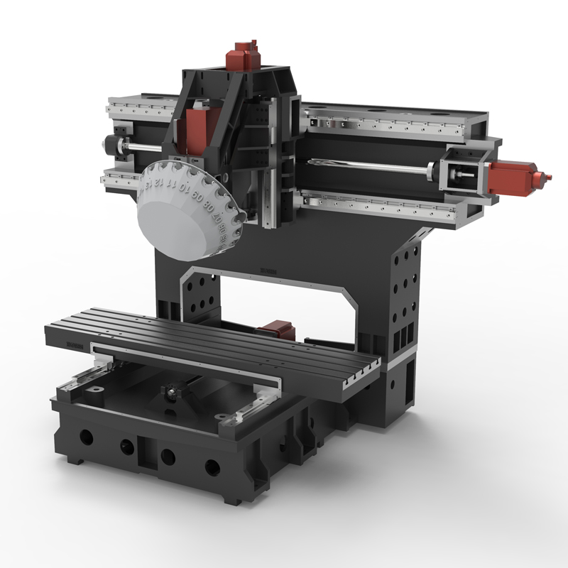
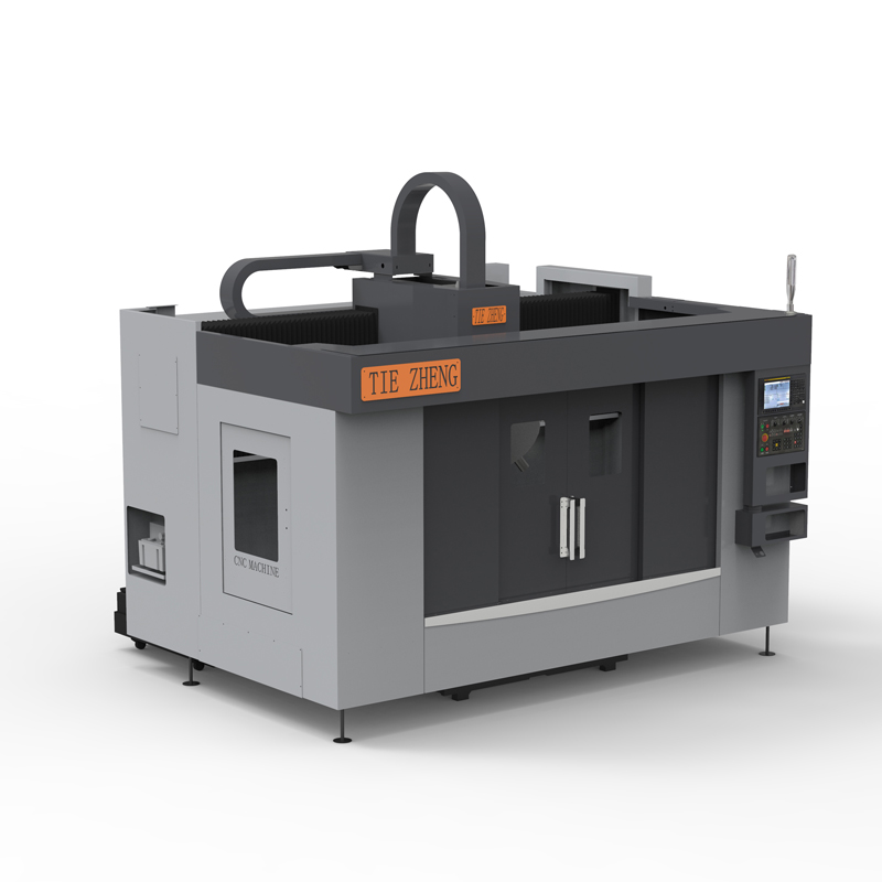
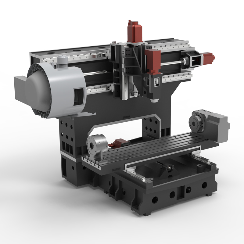
The gantry-type profile drilling and tapping machining center is a piece of equipment specially used for processing profiles. It combines multiple functions such as drilling and tapping to achieve efficient processing operations....
The gantry-type profile drilling and tapping machining center is a piece of equipment specially used for processing profiles. It combines multiple functions such as drilling and tapping to achieve efficient processing operations. The following is a detailed introduction to the gantry profile drilling and tapping machining center:
1. Equipment structure:
The gantry design gives the equipment a large processing range and stability.
Usually equipped with an automatic tool changer, which can quickly change tools and improve processing efficiency.
It has a high-precision positioning and control system to ensure processing accuracy and stability.
2. Processing capacity:
The gantry type profile drilling and tapping machining center is suitable for processing various profiles, including aluminum alloy, steel, copper, etc.
The gantry-type profile drilling and tapping machining center can perform drilling, tapping, milling and other processing operations to meet complex processing needs.
With high processing speed and precision, it can greatly improve production efficiency.
3. Operation and programming:
Gantry profile drilling and tapping machining centers are usually equipped with advanced CNC systems that enable precise programming and control.
The operation interface is friendly, easy to learn and use, and operators can realize complex processing paths and actions through programming.
4. Maintenance and maintenance:
Clean the equipment regularly to keep the appearance of the equipment tidy and prevent dust and debris from affecting the equipment.
The gantry profile drilling and tapping machining center regularly checks the lubrication system of the equipment to ensure that the lubricating oil is clean and sufficient to ensure the normal operation of the equipment.
Regularly check and adjust the accuracy of the equipment to maintain the processing accuracy and stability of the equipment.
5.Safety and protection:
When operating the gantry profile drilling and tapping machining center, you must strictly abide by the safety operating procedures and wear protective equipment.
During the operation of the gantry profile drilling and tapping machining center, it is prohibited to extend hands or other objects into the processing area to prevent accidents.
In general, the gantry profile drilling and tapping machining center is an efficient and stable processing equipment that can meet the processing needs of various profiles. During use, attention needs to be paid to the maintenance and upkeep of the equipment, as well as operational safety, to ensure long-term stable operation of the equipment and processing quality.
| Specifications/model | unit | STA/T1350 | STA/T1650 | STA/T2050 |
| Workbench specifications | ||||
| Workbench size (X-axis direction) | MM | 1600*500 | 1900*500 | 2100*500 |
| X*Y axis travel (left and right) | 1300*500 | 1600*500 | 2000*500 | |
| Distance from spindle nose to work surface | 150-500 | 150-500 | 150-500 | |
| Z-axis heightening (optional) | 300-650 | 300-650 | 300-650 | |
| Maximum load-bearing capacity of workbench | KG | 1300 | 1600 | 2000 |
| Spindle specifications | ||||
| Spindle transmission structure (T type) | / | direct connection | direct connection | direct connection |
| Spindle speed | RPM | 20000 | 20000 | 20000 |
| Spindle horsepower | KW | 5.5 | 5.5 | 5.5 |
| Spindle bore taper | AT | BT30 | BT30 | BT30 |
| Tool changing time T-T | MIN | 1.8 | 1.8 | 1.8 |
| Maximum tool weight | KGS | 6 | 6 | 6 |
| Spindle transmission structure (Type A) | / | direct connection | direct connection | direct connection |
| Spindle speed | RPM | 12000 | 12000 | 12000 |
| Spindle horsepower | KW | 5.5 | 5.5 | 5.5 |
| Spindle inner hole dimensions | AT | BT30 | BT30 | BT30 |
| Tool changing time T-T | MIN | 2.2 | 2.2 | 2.2 |
| Maximum tool weight | KGS | 8 | 8 | 8 |
| Feed content | ||||
| G00 rapid traverse (X/Y/Z) | M/MIN | 32/48/48 | 32/48/48 | 32/48/48 |
| G01 rapid feed | M/MIN | 1-10000 | 1-10000 | 1-10000 |
| Servo motor specifications | NM | 22/22/22B | 22/22/22B | 22/22/22B |
| Servo motor speed | RPM | 2000/3000 | 2000/3000 | 2000/3000 |
| X.Y.Z motor connection method | / | Direct | Direct | Direct |
| Ball screw specifications | MM | 40/40/32 | 40/40/32 | 50/40/32 |
| X-axis rail specifications | MM | 45 ball | 45 ball | 45 ball |
| Y axis rail specifications | MM | 45 ball | 45 ball | 45 ball |
| Z axis rail specifications | MM | 35 ball | 35 ball | 35 ball |
| Precise shaft positioning | MM | ±0.01 | ±0.01 | ±0.01 |
| Repeatable positioning precision | MM | ±0.005 | ±0.005 | ±0.005 |
| Minimum move value | MM | 0.001 | 0.001 | 0.001 |
| Oil and gas pressure system | ||||
| air pressure | KG | 6.5 | 6.5 | 6.5 |
| Lubricating oil capacity | L | 4 | 4 | 4 |
| battery capacity | KW | 25 | 25 | 25 |
| coolant capacity | L | 320 | 320 | 320 |
| Form factor | ||||
| Machine weight (approx.) | KG | 7000 | 8500 | 10000 |
| Machine length (front and rear) | MM | 2500 | 2500 | 2500 |
| Machine width (left and right) | MM | 2300 | 2600 | 3200 |
| Machine height (maximum) | MM | 2500 | 2500 | 2500 |
| Machine height (minimum) | MM | 2200 | 2200 | 2200 |
| Chip removal method | / | backlash | backlash | backlash |

 English
 日本語
日本語 한국어
한국어 Россия
  Français
 España
 عرب .
عرب .  Português
 Deutsch
 भारत
भारत Нидерланды
