- contact us
- Sales Manager:
Asia Li - Email:
asia.cncmachine@gmail.com - Wechat ID:
Asia-Li_90727( +8613210773378) TEL:+8613210773378 - TEL:
8613210773378 - Whatsapp:
8613210773378
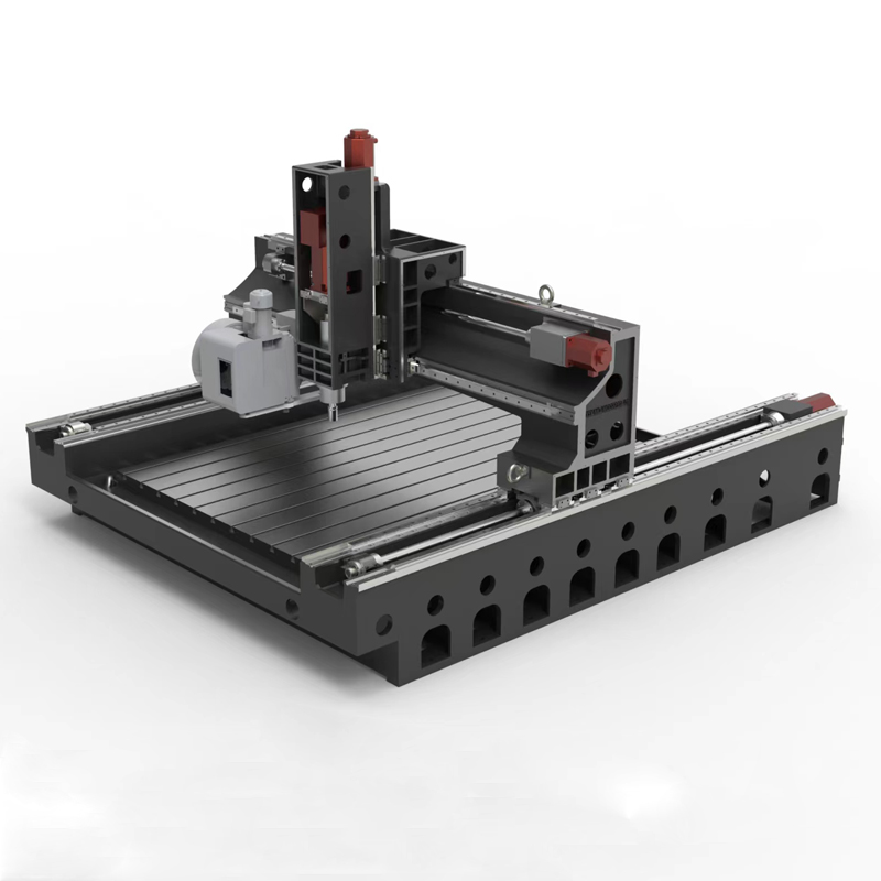
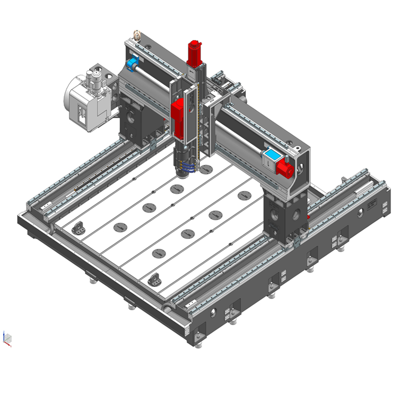
High precision gantry machining center
The high-precision gantry machining center is an efficient and precise CNC machine tool. The high-precision gantry machining center adopts a gantry structure. This structure has beams and columns, allowing it to perform precise movements on three coordinate axes, thereby achieving complex Processing of parts....
The high-precision gantry machining center is an efficient and precise CNC machine tool. The high-precision gantry machining center adopts a gantry structure. This structure has beams and columns, allowing it to perform precise movements on three coordinate axes, thereby achieving complex Processing of parts. High-precision gantry machining center plays an important role in aerospace, automobile manufacturing, mold manufacturing, electronics and other industries.
The high-precision gantry machining center can achieve high-precision machining mainly due to its advanced CNC technology and high-precision transmission system. The worktable of the high-precision gantry machining center uses a high-precision grating ruler for position detection and closed-loop control, which ensures the position accuracy and shape accuracy of the processed parts. At the same time, the high-precision spindle and bearing seat system of the high-precision gantry machining center also ensures stability and accuracy during the machining process.
In addition to high precision, high efficiency is also a distinguishing feature of high-precision gantry machining centers. The high-precision gantry machining center worktable is driven by a high-power motor, which can move quickly and perform high-intensity cutting. In addition, the multi-axis linkage processing capability of the high-precision gantry machining center enables the high-precision gantry machining center to complete the processing of multiple surfaces at one time, greatly reducing processing time and costs.
The application of high-precision gantry machining centers has promoted the technological upgrading and industrial upgrading of the manufacturing industry, and improved the competitiveness of the entire industry. At the same time, the high flexibility and adaptability of the high-precision gantry machining center also enables it to cope with various complex and changing processing needs, providing strong support for the innovative development of enterprises.
In general, the high-precision gantry machining center is an indispensable and important equipment in modern manufacturing. With its high precision and high efficiency, the high-precision gantry machining center provides powerful processing capabilities for various industries and promotes the Development and progress of manufacturing industry.
| Processing specifications/machine models | unit | SMA/T1612 | SMA/T1620 | SMA/T1625 | SMA/T2025 | SMA/T2030 | SMA/T2080 | SMA/T2530 | SMA/T2540 | SMA/T3050 | SMA/T3060 |
| Work content | |||||||||||
| working desk size | MM | 1600*1200 | 1600*2000 | 1600*2500 | 2000*2500 | 2000*3000 | 2000*8000 | 2500*3000 | 2500*4000 | 3000*5000 | 3000*6000 |
| X*Y axis travel | MM | 1600*1200 | 1600*2000 | 1600*2500 | 2000*2500 | 2000*3000 | 2000*8000 | 2500*3000 | 2500*4000 | 3000*5000 | 3000*6000 |
| Z-axis travel (up and down) | MM | 350 | 350 | 350 | 550 | 550 | 550 | 550 | 550 | 550 | 550 |
| Distance between worktable and nose of spindle | MM | 100-450 | 100-450 | 100-450 | 170-720 | 170-720 | 170-720 | 170-720 | 170-720 | 170-720 | 170-720 |
| Gantry width | MM | 1300 | 1300 | 1300 | 2200 | 2200 | 2200 | 2700 | 2700 | 3200 | 3200 |
| Maximum load of workbench | T | 1 | 1.3 | 1.6 | 4 | 5 | 10 | 5 | 6 | 8 | 8 |
| Spindle specifications | BT | BT40 direct connection | BT40 direct connection | BT40 direct connection | BT40 direct connection | BT40 direct connection | BT40 direct connection | BT40 direct connection | BT40 direct connection | BT40 direct connection | BT40 direct connection |
| Spindle transmission structure | / | Mechanical spindle | Mechanical spindle | Mechanical spindle | Mechanical spindle | Mechanical spindle | Mechanical spindle | Mechanical spindle | Mechanical spindle | Mechanical spindle | Mechanical spindle |
| Spindle speed | RPM | 12000 | 12000 | 12000 | 12000 | 12000 | 12000 | 12000 | 12000 | 12000 | 12000 |
| Select the model and speed of the electric spindle | HSK | A63 | A63 | A63 | A63 | A63 | A63 | A63 | A63 | A63 | A63 |
| Spindle speed | RPM | 18000 | 18000 | 18000 | 18000 | 18000 | 18000 | 18000 | 18000 | 18000 | 18000 |
| Tool magazine structure A (specify when ordering) | PCS | disc type | disc type | disc type | Robotic arm disc | Robotic arm disc | Robotic arm disc | Robotic arm disc | Robotic arm disc | Robotic arm disc | Robotic arm disc |
| Tool magazine capacity | BT40-24T | BT40-24T | BT40-24T | BT40-24T | BT40-24T | BT40-24T | BT40-24T | BT40-24T | BT40-24T | BT40-24T | |
| Tool changing time T-T | MM | 2.2 | 2.2 | 2.2 | 2.2 | 2.2 | 2.2 | 2.2 | 2.2 | 2.2 | 2.2 |
| Tool magazine structure T (specify when ordering) | Clamp type | Clamp type | Clamp type | Clamp type | Clamp type | Clamp type | Clamp type | Clamp type | Clamp type | Clamp type | |
| Tool magazine capacity | BT40-16T | BT40-16T | BT40-16T | BT40-16T | BT40-16T | BT40-16T | BT40-16T | BT40-16T | BT40-16T | BT40-16T | |
| Tool changing time T-T | MM | 1.8 | 1.8 | 1.8 | 1.8 | 1.8 | 1.8 | 1.8 | 1.8 | 1.8 | 1.8 |
| Maximum tool weight | KG | 8 | 8 | 8 | 8 | 8 | 8 | 8 | 8 | 8 | 8 |
| Feed content | |||||||||||
| G00 rapid traverse (X/Y axis) | M/MIN | 32.48 | 32.48 | 32.48 | 32.48 | 32.48 | 32.48 | 32.48 | 32.48 | 32.48 | 32.48 |
| G00 Y-axis rack rapid feed | MM/MIN | / | / | / | 48 | 48 | 48 | 48 | 48 | 48 | 48 |
| G00 Y-axis screw rapid feed | MM/MIN | 36 | 36 | 36 | 20 | 20 | 20 | 20 | 20 | 20 | 20 |
| G01 cutting feed | MM/MIN | 1-30000 | 1-30000 | 1-30000 | 1-30000 | 1-30000 | 1-30000 | 1-30000 | 1-30000 | 1-30000 | 1-30000 |
| Servo motor specifications | NM | 22.22.22B | 22.22.22B | 22.22.22B | 22.22.22B | 22.22.22B | 22.22.22B | 22.22.22B | 30.30.22B | 30.30.22B | 30.30.22B |
| Servo motor speed | RPM | 2000/3000 | 2000/3000 | 2000/3000 | 2000/3000 | 2000/3000 | 2000/3000 | 2000/3000 | 2000/3000 | 2000/3000 | 2000/3000 |
| X.Y.Z motor connection method | / | Direct | Direct | Direct | Direct | Direct | Direct | Direct | Direct | Direct | Direct |
| X.Z axis ball screw specifications | MM | 50-40 | 50-40 | 50-40 | 50-40 | 50-40 | 50-40 | 50-40 | 50-40 | 63-40 | 63-40 |
| Y-axis structure | / | Single drive | Single drive | Single drive | Single drive/dual drive | Single drive/dual drive | Dual drive | Dual drive | Dual drive | Dual drive | Dual drive |
| Y-axis rack (standard) specifications | M | / | M3/1:10 | M3/1:10 | M3/1:10 | M3/1:10 | M3/1:10 | M3/1:10 | M3/1:10 | ||
| Y-axis screw (standard) specifications | MM | 5020 | 5020 | 5020 | 5020 | 5020 | 5020 | 6320 | / | / | / |
| X-axis rail specifications | MM | 45 ball | 45 ball | 45 ball | 45 ball | 45 ball | 45 ball | 45 ball | 45 ball | 45 ball | 45 ball |
| Y axis rail specifications | MM | 45 ball | 45 ball | 45 ball | 45 ball | 45 ball*2 | 45 ball*2 | 45 ball*2 | 45 ball*2 | 45 ball*2 | 45 ball*2 |
| Z axis rail specifications | MM | 35 ball | 35 ball | 35 ball | 35 ball | 35 ball | 35 ball | 35 ball | 35 ball | 35 ball | 35 ball |
| Precise positioning of X.Z axis items | MM | ±0.01 | ±0.01 | ±0.01 | ±0.01 | ±0.01 | ±0.01 | ±0.01 | ±0.01 | ±0.01 | ±0.01 |
| X.Z axis repeat position precision | MM | ±0.005 | ±0.005 | ±0.005 | ±0.005 | ±0.005 | ±0.005 | ±0.005 | ±0.005 | ±0.005 | ±0.005 |
| Y-axis positioning accuracy | MM | ±0.02 | ±0.02 | ±0.02 | ±0.02 | ±0.02 | ±0.02 | ±0.02 | ±0.02 | ±0.02 | ±0.02 |
| Minimum move value | MM | 0.001 | 0.001 | 0.001 | 0.001 | 0.001 | 0.001 | 0.001 | 0.001 | 0.001 | 0.001 |
| Oil and gas pressure system | |||||||||||
| air pressure | KG/MM | 6.5 | 6.5 | 6.5 | 6.5 | 6.5 | 6.5 | 6.5 | 6.5 | 6.5 | 6.5 |
| Bed block height | MM | 40 | 40 | 40 | 40 | 40 | 40 | 40 | 40 | 40 | 40 |
| Lubricating oil capacity | L | 4 | 4 | 4 | 4 | 4 | 4 | 4 | 4 | 4 | 4 |
| battery capacity | KW | 25 | 25 | 25 | 25 | 25 | 25 | 30 | 30 | 30 | 30 |
| coolant capacity | L | 180 | 180 | 180 | 220 | 220 | 220 | 320 | 320 | 320 | 320 |
| Form factor | |||||||||||
| Machine weight | T | 8 | 10 | 12 | 14 | 16 | 48 | 18 | 23 | 32 | 36 |
| Machine length | MM | 2200 | 3000 | 3300 | 4000 | 4500 | 10000 | 4300 | 5000 | 6000 | 7000 |
| Machine width | 2300 | 2300 | 2300 | 3200 | 3200 | 3200 | 2800 | 2800 | 3600 | 3600 | |
| Machine height (maximum) | MM | 1800 | 1800 | 1800 | 2100 | 2100 | 2100 | 2100 | 2100 | 2100 | 2100 |
| Machine height (minimum) | MM | 1300 | 1300 | 1300 | 1800 | 1800 | 1800 | 1800 | 1800 | 1800 | 1800 |
| Chip removal method (optional) | / | Twin screw | Twin screw | Twin screw | Twin screw | Twin screw | Twin screw | Twin screw | Twin screw | Twin screw | Twin screw |

 English
 日本語
日本語 한국어
한국어 Россия
  Français
 España
 عرب .
عرب .  Português
 Deutsch
 भारत
भारत Нидерланды
