- contact us
- Sales Manager:
Asia Li - Email:
asia.cncmachine@gmail.com - Wechat ID:
Asia-Li_90727( +8613210773378) TEL:+8613210773378 - TEL:
8613210773378 - Whatsapp:
8613210773378
High speed and light gantry machining center
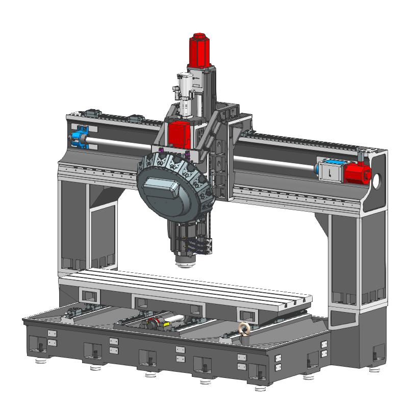
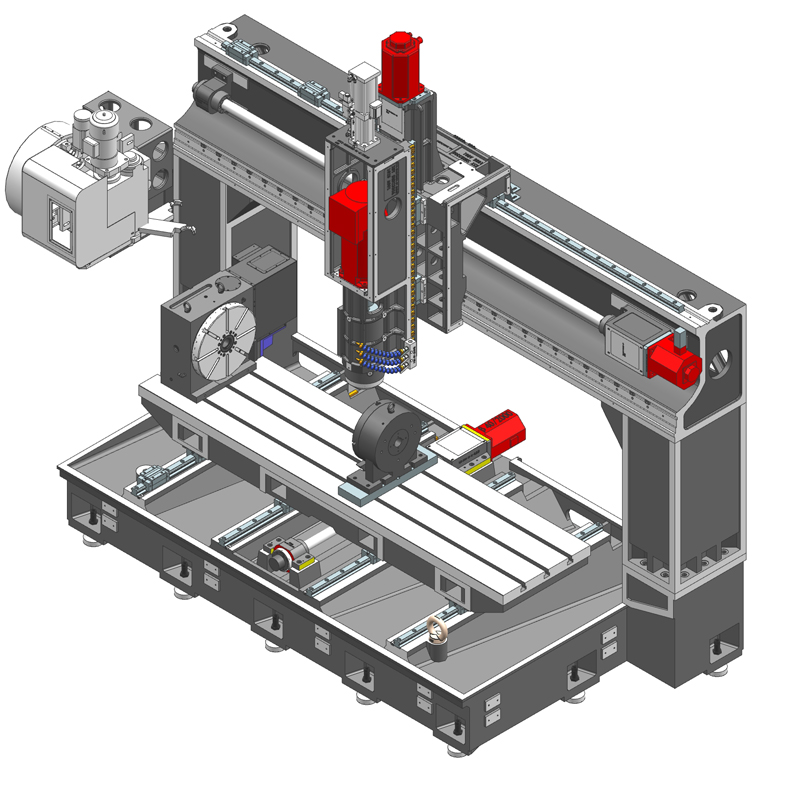
The high-speed and lightweight gantry machining center is a machine tool equipment that combines the characteristics of high-speed cutting and lightweight structure....
The high-speed and lightweight gantry machining center is a machine tool equipment that combines the characteristics of high-speed cutting and lightweight structure. The high-speed and lightweight gantry machining center maintains high precision and efficiency while having a lighter body design, making it more flexible and convenient during the machining process.
The high-speed and lightweight gantry machining center is mainly used to process workpieces of various complex shapes, and is especially suitable for fields with high requirements for machining accuracy and efficiency. For example, in the field of aerospace, high-speed and light gantry machining centers can be used to process high-precision and high-complexity aircraft parts; in the field of automobile manufacturing, high-speed and light gantry machining centers can be used to produce key components such as engines and transmissions; in mold manufacturing In the field of electronics, high-speed and light-weight gantry machining centers can achieve efficient and high-precision processing of molds; in the electronics field, high-speed and light-weight gantry machining centers can also be used to process various precision electronic components.
Its main features include:
1. High precision: The high-speed and lightweight gantry machining center adopts advanced control systems and precise transmission systems to ensure high-precision processing under high-speed cutting and heavy loads.
2. Large span: The span of high-speed lightweight gantry machining centers is usually larger, and multiple large parts can be clamped at one time, reducing the number of clamping times and processing errors, and improving processing efficiency and accuracy.
3. Multi-axis linkage: High-speed and lightweight gantry machining centers usually adopt multi-axis linkage technology, which can realize the processing of complex curved surfaces and improve the freedom and flexibility of processing.
In addition, the body design of the high-speed and lightweight gantry machining center also takes into account the structural stability and thermal deformation issues. By optimizing material selection, structural layout and cooling system, it ensures that the machine tool can still perform under long-term and high-intensity working conditions. Maintain stable processing accuracy.
It should be noted that the price of high-speed light gantry machining center may be affected by various factors such as equipment specifications, performance, brand, and market supply and demand, so the specific price may vary. If you have purchase needs, it is recommended to contact a professional machine tool manufacturer or supplier to obtain the latest quotation and detailed information.
In general, high-speed and lightweight gantry machining centers play an increasingly important role in modern manufacturing due to their high precision, high efficiency, flexibility and convenience.
| Specifications/model | unit | SFA/T1512 | SFA/T2012 | SFA/T2016 | SFA/2512T | SFA/T2516 | SFA/T3012 | SFA/T3016 |
| Work content | ||||||||
| Workbench size (X-axis direction) | MM | 1500*1200 | 2000*12000 | 2000*16000 | 2500*1200 | 1500*1600 | 3000*1200 | 3000*1600 |
| X*Y axis travel | MM | 1600*1200 | 2100*120 | 2100*1600 | 2600*1200 | 2600*1600 | 3100*1200 | 3100*1600 |
| Gantry width | MM | 1650 | 2230 | 2230 | 2730 | 2730 | 3230 | 3230 |
| Z-axis travel (up and down) | MM | 550 | 550 | 550 | 550 | 550 | 550 | 550 |
| Distance from spindle nose to work surface | MM | 170-720 | 170-720 | 170-720 | 170-720 | 170-720 | 170-720 | 170-720 |
| Maximum load of workbench | T | 1 | 1 | 1 | 1.5 | 1.5 | 2 | 2 |
| Spindle content type A | ||||||||
| Spindle specifications | BT | BT40 direct connection | BT40 direct connection | BT40 direct connection | BT40 direct connection | BT40 direct connection | BT40 direct connection | BT40 direct connection |
| Spindle transmission structure | / | Mechanical spindle | Mechanical spindle | Mechanical spindle | Mechanical spindle | Mechanical spindle | Mechanical spindle | Mechanical spindle |
| Spindle speed | RPM | 12000 | 12000 | 12000 | 12000 | 12000 | 12000 | 12000 |
| Optional model speed of electric spindle | HSK | A63 | A63 | A63 | A63 | A63 | A63 | A63 |
| Spindle speed | RPM | 18000 | 18000 | 18000 | 18000 | 18000 | 18000 | 18000 |
| Tool magazine structure A (specify when ordering) | PCS | Robotic arm disc | Robotic arm disc | Robotic arm disc | Robotic arm disc | Robotic arm disc | Robotic arm disc | Robotic arm disc |
| Tool magazine capacity | BT40-24T | BT40-24T | BT40-24T | BT40-24T | BT40-24T | BT40-24T | BT40-24T | |
| Tool changing time T-T | MM | 2.2 | 2.2 | 2.2 | 2.2 | 2.2 | 2.2 | 2.2 |
| Tool magazine structure T (specify when ordering) | / | Clamp type | Clamp type | Clamp type | Clamp type | Clamp type | Clamp type | Clamp type |
| Tool magazine capacity | T | BT40-16T | BT40-16T | BT40-16T | BT40-16T | BT40-16T | BT40-16T | BT40-16T |
| Tool changing time T-T | MM | 1.8 | 1.8 | 1.8 | 1.8 | 1.8 | 1.8 | 1.8 |
| Maximum tool weight | KG | 8 | 8 | 8 | 8 | 8 | 8 | 8 |
| Feed content | ||||||||
| G00 rapid traverse (three axes) | m/min | 36.48.48 | 36.48.48 | 36.48.48 | 36.48.48 | 36.48.48 | 36.48.48 | 36.48.48 |
| G01 cutting feed | mm/min | 1-30000 | 1-30000 | 1-30000 | 1-30000 | 1-30000 | 1-30000 | 1-30000 |
| Servo motor specifications | NM | 22.22.22B | 22.22.22B | 22.22.22B | 22.22.22B | 22.30.22B | 30.30.22B | 30.30.22B |
| Servo motor speed | RPM | 3000 | 3000 | 3000 | 3000 | 2000 | 3000 | 2000 |
| X.Y.Z motor connection method | / | Direct | Direct | Direct | Direct | Direct | Direct | Direct |
| X.Y.Z axis ball screw specifications | MM | 50.50.40 | 50.50.40 | 50.50.40 | 50.50.40 | 50.50.40 | 50.50.40 | 50.50.40 |
| Y-axis rack (optional) specifications | ||||||||
| X-axis rail specifications | MM | 45 ball | 45 ball | 45 ball | 45 ball | 45 ball | 45 ball | 45 ball |
| Y axis rail specifications | MM | 45 balls*2 | 45 balls*4 | 45 balls*4 | 45 balls*4 | 45 balls*4 | 45 balls*4 | 45 balls*4 |
| Z axis rail specifications | MM | 35 ball | 35 ball | 35 ball | 35 ball | 35 ball | 35 ball | 35 ball |
| Precise shaft positioning | MM | ±0.01 | ±0.01 | ±0.01 | ±0.01 | ±0.01 | ±0.01 | ±0.01 |
| Repeatable positioning precision | MM | ±0.005 | ±0.005 | ±0.005 | ±0.005 | ±0.005 | ±0.005 | ±0.005 |
| Minimum move value | MM | 0.001 | 0.001 | 0.001 | 0.001 | 0.001 | 0.001 | 0.001 |
| Oil and gas pressure system | ||||||||
| air pressure | KG/MM | 6.5 | 6.5 | 6.5 | 6.5 | 6.5 | 6.5 | 6.5 |
| Bed block height | MM | 40 | 40 | 40 | 40 | 40 | 40 | 40 |
| Lubricating oil capacity | L | 4 | 4 | 4 | 4 | 4 | 4 | 4 |
| battery capacity | KW | 30 | 30 | 30 | 30 | 30 | 30 | 30 |
| coolant capacity | L | 260 | 260 | 300 | 260 | 300 | 260 | 300 |
| Form factor | ||||||||
| Machine weight (approx.) | T | 9 | 10 | 12 | 12 | 14 | 14 | 17 |
| Machine length (front and rear) | MM | 3000 | 3500 | 4200 | 3500 | 4200 | 3500 | 4200 |
| Machine width (left and right) | MM | 3000 | 3500 | 3500 | 4000 | 4000 | 4500 | 4500 |
| Machine height (maximum) | MM | 3500 | 3500 | 3500 | 3500 | 3500 | 3500 | 3500 |
| Machine height (minimum) | MM | 3300 | 3300 | 3300 | 3300 | 3300 | 3300 | 3300 |
| Chip removal method (optional) | / | High voltage rear row | High voltage rear row | High voltage rear row | High voltage rear row | High voltage rear row | High voltage rear row | High voltage rear row |

 English
 日本語
日本語 한국어
한국어 Россия
  Français
 España
 عرب .
عرب .  Português
 Deutsch
 भारत
भारत Нидерланды
