- contact us
- Sales Manager:
Asia Li - Email:
asia.cncmachine@gmail.com - Wechat ID:
Asia-Li_90727( +8613210773378) TEL:+8613210773378 - TEL:
8613210773378 - Whatsapp:
8613210773378
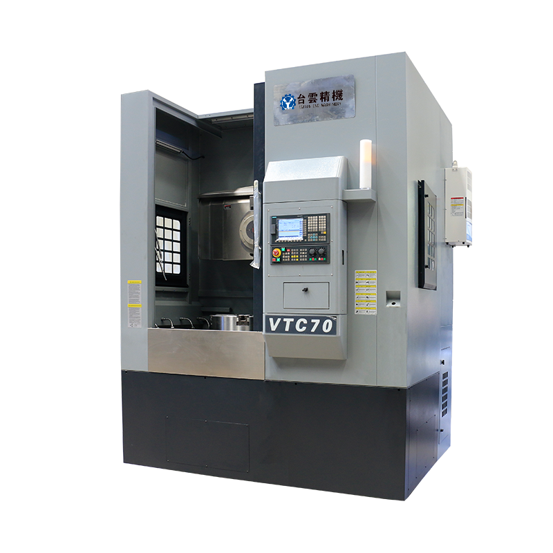
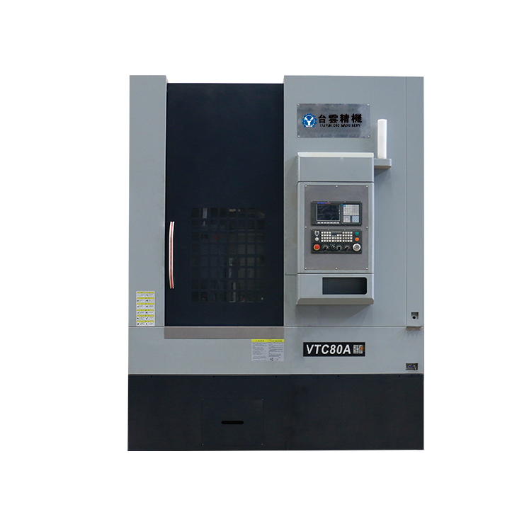
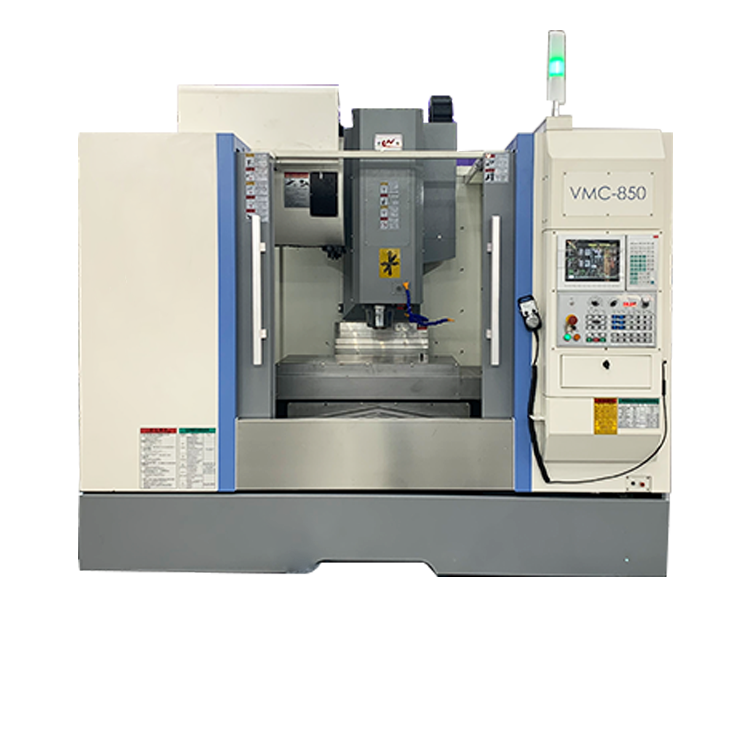
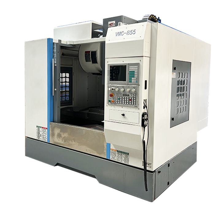
Special machining center for high-precision parts
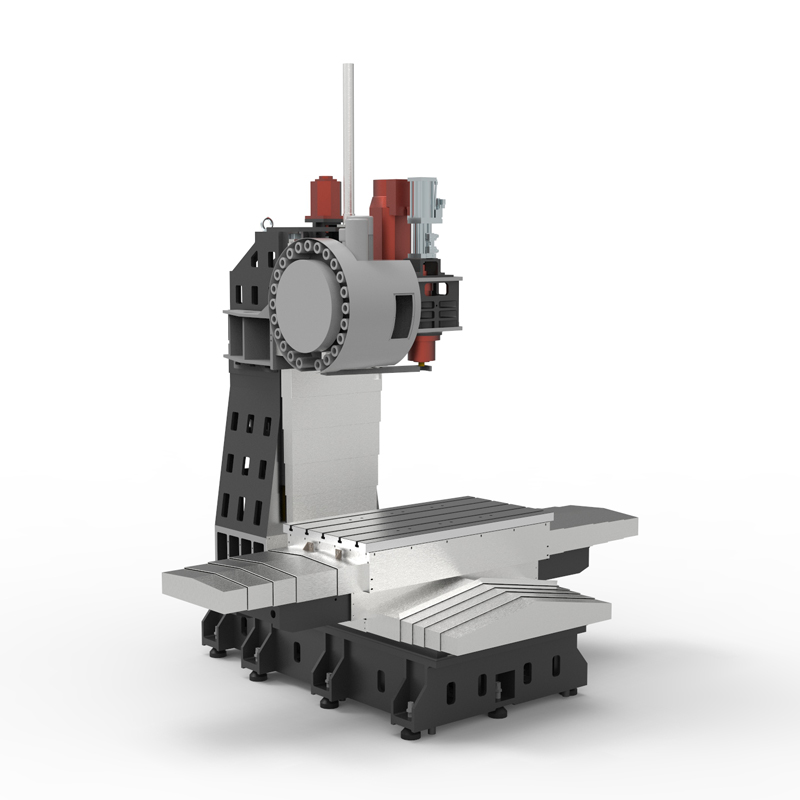
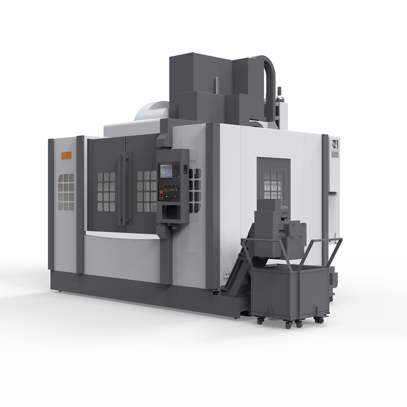
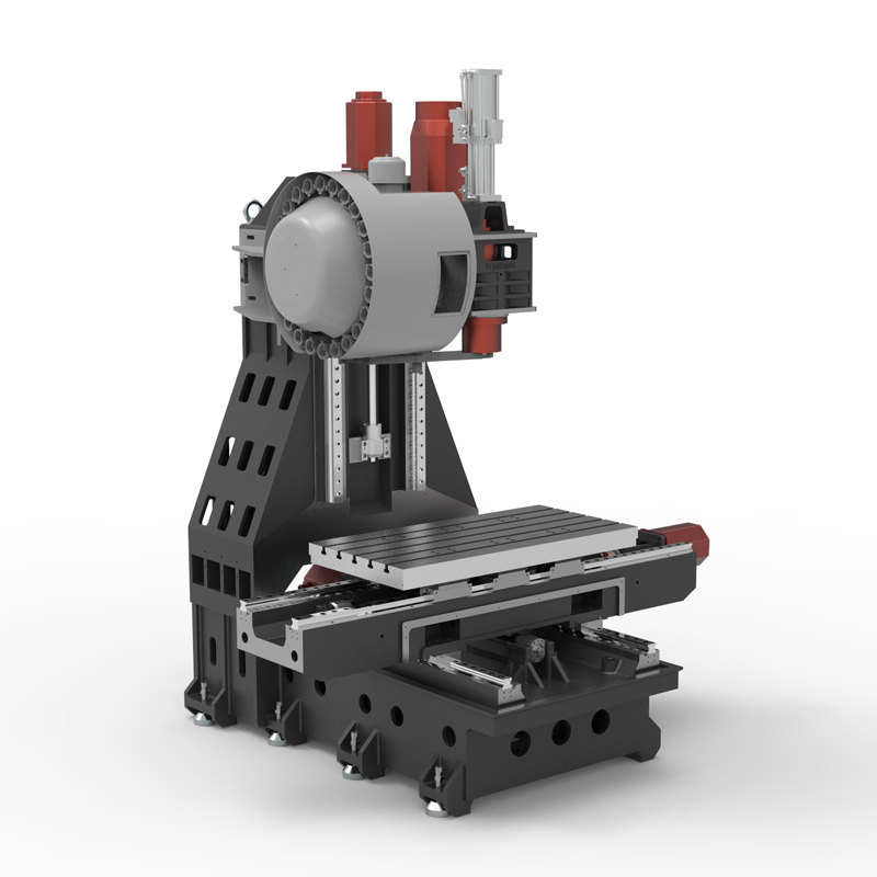
The special machining center for high-precision parts is a machine tool that uses advanced CNC technology for automated processing and is specially designed for the processing of high-precision parts....
The special machining center for high-precision parts is a machine tool that uses advanced CNC technology for automated processing and is specially designed for the processing of high-precision parts. It has a variety of functions and features to meet the special needs of high-precision parts processing.
First of all, the dedicated machining center for high-precision parts has high-precision processing capabilities. Through a precise CNC system and advanced mechanical structure, it can achieve micron-level or even nano-level processing of parts, ensuring that the dimensional accuracy and shape accuracy of the parts reach extremely high standards.
Secondly, the special machining center for high-precision parts has multi-axis processing capabilities. It can realize multi-axis linkage and complete complex curved surface processing, special-shaped hole processing and other tasks, thereby meeting the diverse processing needs of high-precision parts.
In addition, the special machining center for high-precision parts also has functions such as automatic tool changing and automatic measurement. Through the automatic tool changer, multiple processes can be completed in one clamping, thereby improving processing efficiency. At the same time, the automatic measurement function can monitor dimensional changes during processing in real time to ensure processing accuracy and stability.
In terms of software, special machining centers for high-precision parts are usually equipped with advanced CNC programming systems and motion control cards, which can realize complex processing trajectory control and customized motion trajectory programming. This makes the processing process more flexible and efficient, and can meet the processing needs of different high-precision parts.
Finally, special machining centers for high-precision parts are widely used in aerospace, optics, biomedicine, semiconductor and other fields that require high-precision processing. It is capable of handling a variety of materials, including metals, non-metals and composites, and is highly flexible and adaptable to handle part machining challenges of different shapes and sizes.
To sum up, the special machining center for high-precision parts is a machine tool equipment with advanced features such as high-precision machining capabilities, multi-axis machining capabilities, automatic tool change, and automatic measurement functions. It can meet the special needs of high-precision parts processing and provide efficient and reliable processing solutions for related industries.
| Specifications/model | unit | V966 | V1160 | V1168 | V1270 | V1377 | V1387 | V1380C | V1680C | V2010C |
| Work content | ||||||||||
| working desk size | MM | 1100×700 | 1200×600 | 1200×600 | 1300×700 | 1400×7010 | 1400×800 | 1400×800 | 1700×800 | 2100×1000 |
| Workbench travel (X/Y/Z) | MM | 900×600×600 | 1100×600×600 | 1100×600×800 | 1200×700×600 | 1300×700×700 | 1300×800×700 | 1300×800×70 | 1600×800×700 | 2000×1000×800 |
| Distance from spindle nose to work surface | MM | 150-750 | 120-720 | 120-920 | 120-720 | 120-820 | 120-820 | 150-850 | 150-850 | 150-950 |
| Distance from spindle center to column track surface | MM | 700 | 660 | 660 | 780 | 780 | 900 | 900 | 900 | 1100 |
| Maximum load of workbench | KG | 700 | 1000 | 1000 | 1100 | 1300 | 1400 | 1500 | 1800 | 2200 |
| Spindle specifications | ||||||||||
| Spindle transmission structure (standard) | / | Belt type | Belt type | Belt type | Belt type | Belt type | Belt type | Belt type | Belt type | Belt type |
| Spindle speed | RPM | 8000 | 8000 | 8000 | 8000 | 8000 | 8000 | 6000 | 6000 | 6000 |
| Spindle transmission structure (optional) | / | direct connection | direct connection | direct connection | direct connection | direct connection | direct connection | direct connection | direct connection | direct connection |
| Spindle speed | RPM | 12000 | 12000 | 12000 | 10000 | 10000 | 10000 | 10000 | 10000 | 10000 |
| Spindle power | KW | 11 | 11 | 11 | 15 | 15 | 15 | 15/18.5 | 18.5/22 | 18.5/22 |
| Spindle bore taper | BT | BT40-150 | BT40-150 | BT40-150 | BT40-150 | BT40-150 | BT40-150 | BT50-190 | BT50-190 | BT50-190 |
| Feed content | ||||||||||
| G00 rapid feed | M/MIN | 48/48/48 | 36/36/36 | 36/36/36 | 32/32/32 | 32/32/32 | 32/32/32 | 24/24/24 | 24/24/24 | 24/24/24 |
| G01 cutting feed | MM/MIN | 1-10000 | 1-10000 | 1-10000 | 1-10000 | 1-10000 | 1-10000 | 1-10000 | 1-10000 | 1-10000 |
| Servo motor specifications | NM | 22/22/22B | 22/22/22B | 22/22/22B | 22/22/22B | 22/22/22B | 22/22/22B | 40/30/30B | 40/30/30B | 40/30/30B |
| Servo motor speed | RPM | 3000 | 3000 | 3000 | 3000 | 3000 | 3000 | 2000 | 2000 | 002000 |
| Motor connection method | / | Direct | Direct | Direct | Direct | Direct | Direct | Direct | Direct | Direct |
| Ball screw specifications | MM | 4016/12 | 4012 | 4012 | 4012 | 4012 | 4012 | 5010 | 5010 | 5010/6310 |
| X-axis rail specifications | MM | 45 roller | 45*3 roller | 45*3 roller | 45*3 roller | 45*3 roller | 45*3 roller | 55*3 roller | 55*3 roller | 55*3 roller |
| Y axis rail specifications | MM | 45 roller | 45 roller | 45 roller | 45 roller | 45 roller | 45 roller | 45 rollers*4 rails | 45 rollers*4 rails | 45 rollers*4 rails |
| Z axis rail specifications | MM | 45*3 roller | 45*3 roller | 45*3 roller | 45*3 roller | 45*3 roller | 45*3 roller | 55*3 roller | 55*3 roller | 55*3 roller |
| Z-axis VB hard rail (optional) | / | hard rail | hard rail | hard rail | hard rail | hard rail | hard rail | hard rail | hard rail | hard rail |
| Precise shaft positioning | MM | ±0.005/300 | ±0.005/300 | ±0.005/300 | ±0.005/300 | ±0.005/300 | ±0.005/300 | ±0.005/300 | ±0.005/300 | ±0.005/300 |
| Repeatable positioning precision | MM | ±0.003/300 | ±0.003/300 | ±0.003/300 | ±0.003/300 | ±0.003/300 | ±0.003/300 | ±0.003/300 | ±0.003/300 | ±0.003/300 |
| Minimum move value | MM | 0.001 | 0.001 | 0.001 | 0.001 | 0.001 | 0.001 | 0.001 | 0.001 | 0.001 |
| Tool magazine system | ||||||||||
| Tool magazine structure | / | Knife arm type | Knife arm type | Knife arm type | Knife arm type | Knife arm type | Knife arm type | Knife arm type | Knife arm type | Knife arm type |
| Tool magazine capacity | PCS | 24 | 24 | 24 | 24 | 24 | 24 | 24 | 24 | 24 |
| Tool changing time | MM | 2.2 | 2.2 | 2.2 | 2.2 | 2.2 | 2.2 | 3.7 | 3.7 | 4 |
| Maximum tool weight | KG | 8 | 8 | 8 | 8 | 8 | 8 | 18 | 18 | 18 |
| Oil and gas pressure system | ||||||||||
| air pressure | KG/MM | 6.5-8 | 6.5-8 | 6.5-8 | 6.5-8 | 6.5-8 | 6.5-8 | 6.5-8 | 6.5-8 | 6.5-8 |
| Lubricating oil capacity | L | 4 | 4 | 4 | 4 | 4 | 4 | 4 | 4 | 4 |
| battery capacity | KW | 23 | 23 | 23 | 23 | 23 | 23 | 36 | 36 | 36 |
| coolant capacity | L | 250 | 300 | 300 | 300 | 300 | 300 | 370 | 370 | 470 |
| Form factor | ||||||||||
| Machine weight (approx.) | T | 7.5 | 8.5 | 8.8 | 9.2 | 10.2 | 11 | 12.8 | 13.8 | 16 |
| Machine length (front and rear) | MM | 2900 | 2900 | 2900 | 3000 | 3050 | 3050 | 3300 | 3300 | 3600 |
| Machine width (left and right) | MM | 3300 | 3550 | 3850 | 3950 | 4050 | 4250 | 4300 | 4650 | 5400 |
| Machine height (maximum) | MM | 2900 | 2900 | 2900 | 3100 | 3100 | 3100 | 3300 | 3300 | 3400 |
| Machine height (minimum) | MM | 2500 | 2500 | 2500 | 2650 | 2650 | 2620 | 2900 | 2900 | 3000 |
| Chip removal method (optional) | / | single chain plate | single chain plate | single chain plate | single chain plate | single chain plate | single chain plate | single chain plate | single chain plate | single chain plate |
| Chip removal method (optional) | / | Twin screw | Twin screw | Twin screw | Twin screw | Twin screw | Twin screw | Twin screw | Twin screw | Twin screw |

 English
 日本語
日本語 한국어
한국어 Россия
  Français
 España
 عرب .
عرب .  Português
 Deutsch
 भारत
भारत Нидерланды
