- contact us
- Sales Manager:
Asia Li - Email:
asia.cncmachine@gmail.com - Wechat ID:
Asia-Li_90727( +8613210773378) TEL:+8613210773378 - TEL:
8613210773378 - Whatsapp:
8613210773378
Horizontal drilling and milling machine
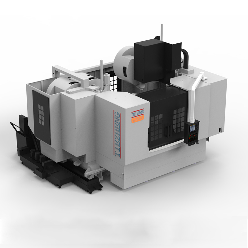
The horizontal drilling and milling machine machining center is a machine tool with its spindle parallel to the worktable in a horizontal position....
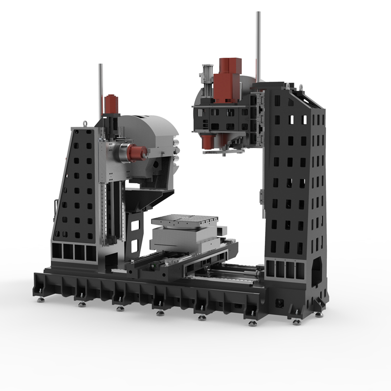
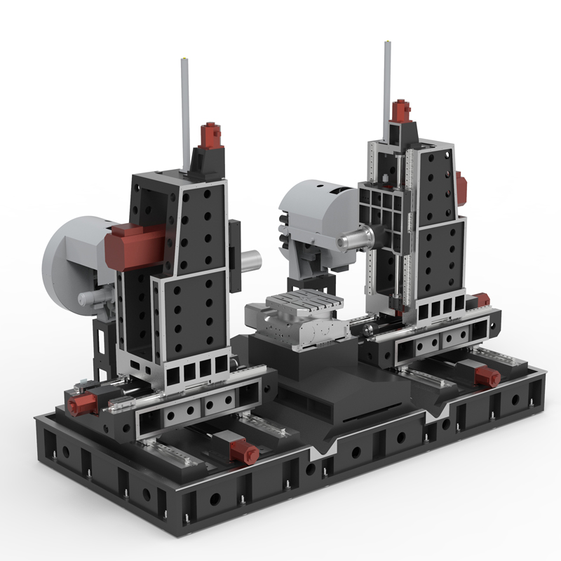
The horizontal drilling and milling machine machining center is a machine tool with its spindle parallel to the worktable in a horizontal position. The working principle of this kind of machine tool is to drive the tool to rotate through the spindle, cut the workpiece, and realize drilling, milling and processing of various complex shapes.
Specifically, the spindle of a horizontal drilling and milling machine machining center is driven by a motor to drive the tool to rotate for cutting, while cutting tools such as drills and milling cutters are fixed on the tool holder or turret and are driven by the spindle to rotate and cut.
When using a horizontal drilling and milling machine center for drilling or milling operations, you need to first check whether the workpiece is firmly fixed and ensure that the tool is perpendicular to the workpiece surface or determine the starting point of milling. Then turn on the main power switch of the horizontal drilling and milling machine machining center, start the spindle motor, adjust the rotation speed and feed speed, and then switch to manual mode for cutting operations. During the operation of the horizontal drilling and milling machine center, you need to pay attention to the amount and direction of the cutting oil injection, and clean the chips in time to avoid accumulation.
In general, the horizontal drilling and milling machine center is a powerful machine tool that is widely used in the processing of various metal materials.
| Specifications/model | Unit | WHH50 | WHH63 | WHH80 | WHH100 |
| Work content | |||||
| Turntable table size WHA | MM | 500×500 | 630×630 | 800×800 | 1000×1000 |
| Fixed table size WHF (optional) | MM | 1000×500 | 1300×600 | 1300×600 | 1600×1000 |
| Number of worktables (optional translational double work) | N | Single/Double | Single/Double | Single/Double | Single/Double |
| Workbench indexing (standard) | N | 1 degree 1 minute | 1 degree 1 minute | 1 degree 1 minute | 1 degree 1 minute |
| Workbench (optional) | N | Other graduations can be customized | Other graduations can be customized | Other graduations can be customized | Other graduations can be customized |
| Maximum rotation diameter of worktable | MM | 1000 | 1300 | 1300 | 1600 |
| X1.X2 axis travel | MM | 800 | 1000 | 1000 | 1300 |
| Y1.Y2 axis travel (spindle item moves up and down) | MM | 700 | 700 | 700 | 700 |
| Z1.Z2 axis stroke | MM | 500 | 900 | 900 | 900 |
| Distance from spindle center to worktable | MM | 110-810 | 110-810 | 110-810 | 110-810 |
| Distance from spindle end face to worktable center | MM | 200-700 | 200-1100 | 200-1100 | 200-1100 |
| T-shaped workbench (slot width * number of slots) | MM | 22-3 | 22-3 | 22-5 | 22-5 |
| Workbench load-bearing | KG | 2000 | 2500 | 3200 | 5000 |
| Spindle and spindle box specifications | |||||
| Spindle taper hole (model/installation dimensions) | ISO | BT40-150 | BT50-190 | BT50-190 | BT50-190 |
| Spindle speed mark (optional) | RPM | 4000/8000/12000 | 4000/6000 | 4000/6000 | 4000/6000 |
| Feeding system | |||||
| X.Y.Z axis screw specifications | MM | 40/40/40 | 50/50/50 | 50/50/50 | 63/50/50 |
| X-axis rapid movement speed | M/MIN | X:48 | X:32 | X:32 | X:24 |
| Y-axis rapid movement speed | M/MIN | Y:48 | Y:32 | Y:32 | Y:24 |
| Z-axis rapid movement speed | M/MIN | Z:48 | Z:32 | Z:32 | Z:24 |
| X/Y/Z axis wire gauge specifications | MM | Roller 45/45/45 | Roller 55/55/55 | Roller 55/55/55 | Roller 55/55/55 |
| X/Y/Z motor connection method | / | direct connection | direct connection | direct connection | direct connection |
| main motor power | KW | 11 | 18.5 | 18.5 | 18.5 |
| X-axis motor power | NM | 22/22B/22 | 27/27B/27 | 27/27B/27 | 30/30B/30 |
| B-axis motor power | NM | B:8 | 12 | 12 | 22 |
| Axis positioning accuracy | MM | ±0.005/300 | ±0.005/300 | ±0.005/300 | ±0.005/300 |
| Axis item repeat positioning accuracy | MM | ±0.003/300 | ±0.003/300 | ±0.003/300 | ±0.003/300 |
| BPositioning accuracy | MM | 8” | 8” | 8” | 8” |
| B Repeat positioning accuracy | MM | 5” | 5” | 5” | 5” |
| Minimum move value | MM | 0.001 | 0.001 | 0.001 | 0.001 |
| Oil and gas pressure system | |||||
| air pressure | KG | 7 | 7 | 7 | 7 |
| coolant capacity | L | 550 | 650 | 650 | 850 |
| Lubricating oil capacity L | L | 4 | 4 | 4 | 4 |
| Toolholder/Tool Magazine System (specify when ordering) | |||||
| Tool magazine structure | / | Robotic arm | Robotic arm | Robotic arm | Robotic arm |
| Number of tool magazines | T | 24 | 24 | 24 | 24 |
| Tool changing time T-T | MM | 3 | 7 | 7 | 7 |
| Maximum tool weight | KGS | 8 | 12 | 12 | 12 |
| Form factor | |||||
| Weight approx. | KG | 10/11 | 19/20 | 21/22 | 28/30 |
| Machine length | MM | 5500 | 7500 | 7500 | 9500 |
| Machine width | MM | 3800 | 4500 | 4500 | 5500 |
| Machine height (maximum) | MM | 3300 | 3700 | 3700 | 4200 |
| Machine height (minimum) | MM | 3000 | 3300 | 3300 | 3600 |
| Chip removal method | / | win screw + single chain plate | win screw + double chain plate | win screw + double chain plate | win screw + double chain plate |

 English
 日本語
日本語 한국어
한국어 Россия
  Français
 España
 عرب .
عرب .  Português
 Deutsch
 भारत
भारत Нидерланды
