- contact us
- Sales Manager:
Asia Li - Email:
asia.cncmachine@gmail.com - Wechat ID:
Asia-Li_90727( +8613210773378) TEL:+8613210773378 - TEL:
8613210773378 - Whatsapp:
8613210773378
Horizontal machining center with reasonable layout
Horizontal machining center is a kind of efficient and precise processing equipment, which is gradually becoming favored by enterprises....
Horizontal machining center is a kind of efficient and precise processing equipment, which is gradually becoming favored by enterprises. The following is a detailed introduction to horizontal machining centers:
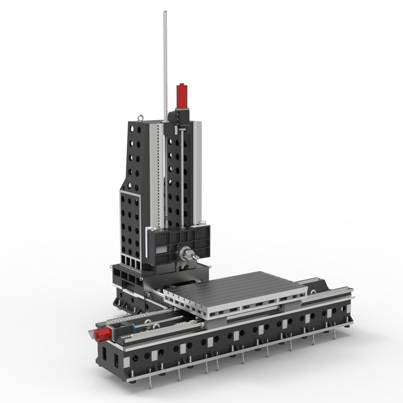
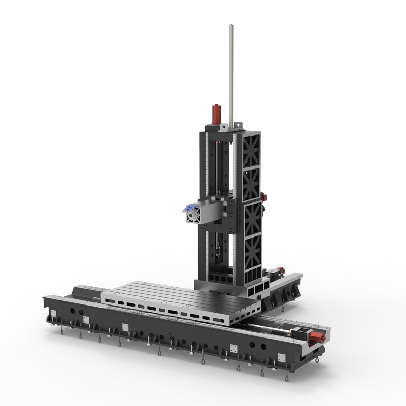
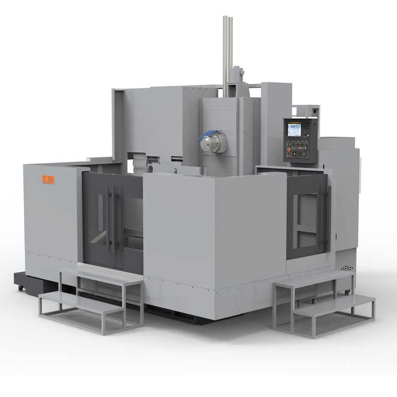
Horizontal machining center refers to a machining center machine tool in which the spindle axis is set parallel to the worktable. It is a commonly used CNC machine tool. The horizontal machining center can process larger parts and perform indexed rotary processing. It is most suitable for multi-process processing such as milling, drilling, boring, reaming, tapping, two-dimensional and three-dimensional curved surfaces of parts. Due to its high technical content, the horizontal machining center is one of the iconic products in the development level of the CNC machine tool industry and has been widely used in various industries.
The working principle of a horizontal machining center mainly includes the rotation of the spindle, movement of the workbench, tool selection and cutting process, and the application of coolant. The spindle has the characteristics of high-speed rotation, driving the cutting tool for cutting. The horizontal machining center table moves in the horizontal direction to control the relative position and cutting path of the workpiece and tool. The horizontal machining center selects appropriate tools for cutting based on the workpiece material and processing requirements. At the same time, the application of coolant in horizontal machining centers helps to reduce the temperature, extend the service life of tools, and ensure processing quality.
The advantages of horizontal machining centers include high processing efficiency, high degree of automation, simple and convenient operation, etc. The horizontal machining center can automatically complete various processing processes such as drilling, milling, cutting, and tapping. It is many times more efficient than manual processing and also reduces the error rate. In addition, horizontal machining centers have easier chip removal and are more beneficial for complex concave and mold cavity processing, so they can process large workpieces and workpieces that are difficult or impossible to process with vertical machining centers.
However, horizontal machining centers also have some disadvantages. For example, it occupies a large area, has a complex structure, and is more expensive than a vertical machining center. In addition, it may be inconvenient to debug the program of a horizontal machining center. It is difficult to observe the movement trajectory of the tool during processing, and it may also be inconvenient to load, unload, and measure the workpiece.
In general, the horizontal machining center is a powerful and widely used processing equipment, suitable for various industries that require efficient and precise processing. When laying out a horizontal machining center, factors such as space utilization, operational convenience, safety, and future scalability should be fully considered to achieve optimal production efficiency and economic benefits.
| Specifications/Models | Unit | WY10 | WY15 | WY20 | WY25 | WY30 | WY40 |
| Work content | |||||||
| Work surface size | MM | 1200×1600 | 1700×800 | 2000×1200 | 2500×1400 | 3000×1400 | 4000×1400 |
| X-axis travel | MM | 1100 | 1600 | 2100 | 2600 | 3100 | 4200 |
| Y-axis spindle box up and down travel (standard/optional) | MM | 700/900 | 700/900 | 1000/1500 | 1000/1500 | 1500/2000 | 1500/2000 |
| Z-axis column front and rear travel (standard, optional) | MM | 800 | 800/1200 | 800/1200 | 800/1200 | 800/1200 | 800/1200 |
| Distance from spindle center to worktable | MM | 120-890 | 120-1120 | 120-1320 | 120-1820 | 120-1820 | 120-2120 |
| Distance from spindle end face to worktable center | MM | 130-1030 | 200-1200 | 400-1600 | 500-1700 | 500-1700 | 700-1700 |
| Workbench slot width + T slot | MM | 5-22 | 9-28 | 9-28 | 11-28 | 11-28 | 11-28 |
| Workbench load-bearing | KG | 1200 | 2500 | 3000 | 6000 | 10000 | 14000 |
| Spindle and spindle specifications | |||||||
| Spindle taper hole | ISO | BT50-190 | BT50-190 | BT50-190 | BT50-190 | BT50-190 | BT50-190 |
| Spindle speed | RPM | 4000/6000 | 4000/6000 | 4000/6000 | 4000/6000 | 4000/6000 | 4000/6000 |
| Type A boring bar specification diameter (optional) | MM | / | 110 | 110 | 130 | 130 | 130 |
| Boring bar stroke Z1 (optional) | MM | / | 550 | 550 | 550 | 550 | 550 |
| Type B square ram specifications square type (optional) | MM | / | / | 320 | 320 | 320 | 320 |
| Square ram stroke Z2 (optional) | MM | / | / | 600 | 600 | 600 | 600 |
| T-shaped workbench (slot width * number of slots) | / | 28*300 | / | 28*300 | 28*300 | 28*300 | 28*300 |
| Feeding system | |||||||
| Shaft Ball Screw Specifications | MM | 40/40/50 | 50/50/50 | 63/50/50 | 63/50/50 | 63/50/50 | 80/63/63 |
| XYZ axis rapid movement speed | M/MIN | 32.32.32 | 32.32.32 | 24.24.24 | 24.24.24 | 20.24.24 | 20.24.24 |
| X/Z axis wire gauge specifications | MM | Roller 55/55 | Roller 55/55 | Roller 55/55 | Roller 55/55 | Roller 55/55 | Roller 55/55 |
| Y-axis wire gauge specifications | MM | Roller 55 | Roller 55 | Roller 45*4 | Roller 45*4 | Roller 45*4 | Roller 45*4 |
| Motor connection method | / | Direct | Direct | Direct connection + reducer | Direct connection + reducer | Direct connection + reducer | Direct connection + reducer |
| Main motor parameter marking/selection | KW | 22/+reducer | 22/+reducer | 22/+reducer | 22/+reducer | 22/+reducer | 22/+reducer |
| Axis positioning accuracy | MM | ±0.005 | ±0.005 | ±0.005 | ±0.005 | ±0.005 | ±0.005 |
| Axis item repeat positioning accuracy | MM | ±0.003 | ±0.003 | ±0.003 | ±0.003 | ±0.003 | ±0.003 |
| Minimum move value | MM | 0.001 | 0.001 | 0.001 | 0.001 | 0.001 | 0.001 |
| Oil and gas pressure system | |||||||
| Spindle box balancing system (vertical installation) | / | gas balance | gas balance | gas balance | gas balance | gas balance | gas balance |
| air pressure | KG/MM | 6.5 | 6.5 | 6.5 | 6.5 | 6.5 | 6.5 |
| coolant capacity | L | 550 | 550 | 550 | 550 | 550 | 550 |
| Lubricating oil capacity L | L | 4 | 4 | 4 | 4 | 4 | 4 |
| Toolholder/Tool Magazine System (specify when ordering) | |||||||
| Tool magazine structure | / | Disc knife arm type | Disc knife arm type | Disc knife arm type | Disc knife arm type | Disc knife arm type | Disc knife arm type |
| Number of tool magazines (optional) | T | 24/32 | 24/32 | 24/32 | 24/32 | 24/32 | 24/32 |
| Knife inventory structure (optional) | / | Chain plate type tool magazine | Chain plate type tool magazine | Chain plate type tool magazine | Chain plate type tool magazine | Chain plate type tool magazine | Chain plate type tool magazine |
| Number of tool magazines | T | 40/50/60/80 | 40/50/60/80 | 40/50/60/80 | 40/50/60/80 | 40/50/60/80 | 40/50/60/80 |
| Tool changing time | MM | 5.2 | 5.2 | 5.2 | 5.2 | 5.2 | 5.2 |
| Maximum tool weight | KGS | 18 | 18 | 18 | 18 | 18 | 18 |
| Form factor | |||||||
| Weight approx. | T | 9 | 13/15 | 16/18 | 22/24 | 24/26 | 32/34 |
| Machine width | MM | 3000 | 4000 | 5000 | 6500 | 7500 | 9700 |
| Machine length | MM | 4500 | 5500 | 5800 | 6300 | 6300 | 7300 |
| Machine height (maximum) | MM | 4100 | 4300 | 5000 | 5500 | 5500 | 6000 |
| Machine tool mechanism | / | Inverted T shape | Inverted T shape | Inverted T shape | Inverted T shape | Inverted T shape | Inverted T shape |
| Chip removal method | / | Twin screw + chain plate | Twin screw + chain plate | Twin screw + chain plate | Twin screw + chain plate | Twin screw + chain plate | Twin screw + chain plate |

 English
 日本語
日本語 한국어
한국어 Россия
  Français
 España
 عرب .
عرب .  Português
 Deutsch
 भारत
भारत Нидерланды
