- contact us
- Sales Manager:
Asia Li - Email:
asia.cncmachine@gmail.com - Wechat ID:
Asia-Li_90727( +8613210773378) TEL:+8613210773378 - TEL:
8613210773378 - Whatsapp:
8613210773378
Multifunctional horizontal machining center
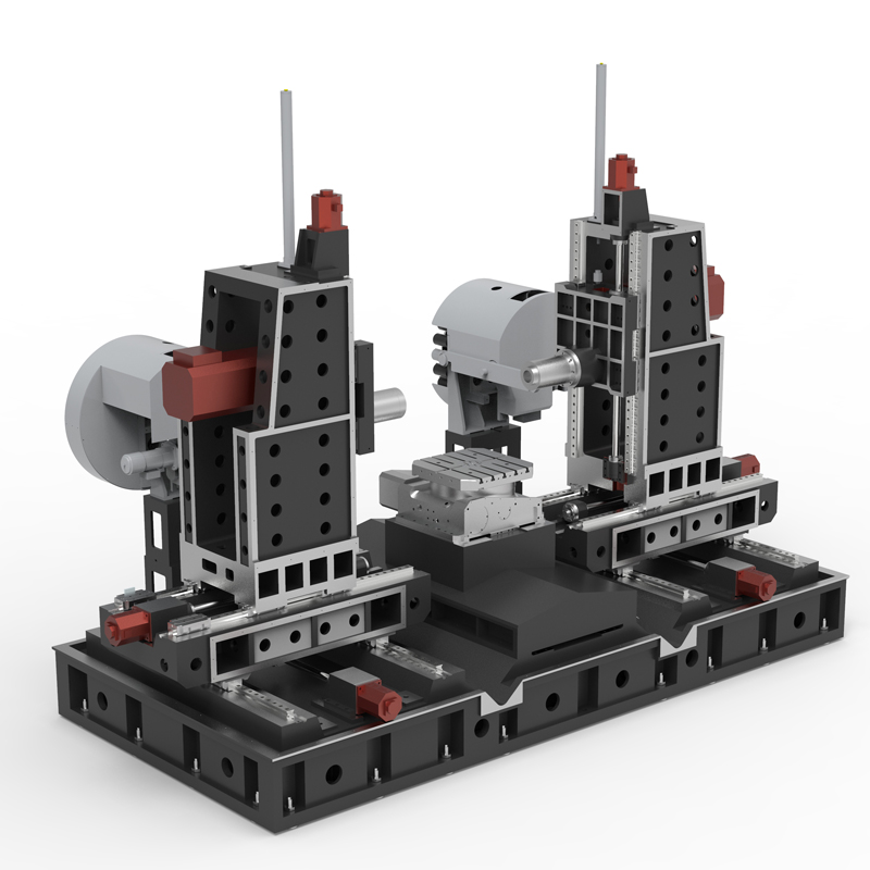
Multifunctional horizontal machining center is a CNC machine tool equipment that integrates multiple processing functions. It has processing functions such as milling, drilling, reaming, reaming, boring, tapping and cutting, and can complete complex three-dimensional curved surfaces....
Multifunctional horizontal machining center is a CNC machine tool equipment that integrates multiple processing functions. It has processing functions such as milling, drilling, reaming, reaming, boring, tapping and cutting, and can complete complex three-dimensional curved surfaces. processing. The multi-functional horizontal machining center adopts a horizontal structure, which makes the workpiece more stable during processing, thus effectively improving the processing accuracy.
Multifunctional horizontal machining centers have a variety of core components, such as high-precision spindles, servo feed systems, tool magazines, and tool changing mechanisms. The high-precision spindle of the multi-functional horizontal machining center ensures the stability and accuracy of the tool when rotating at high speed; the servo feed system achieves precise processing of the workpiece by accurately controlling the feed speed and position; and the tool magazine and tool change mechanism This enables machine tools to quickly change tools to meet different processing needs.
The multi-functional horizontal machining center has powerful automation functions, such as automatic tool change, automatic positioning, automatic detection, etc., which further reduces the degree of manual intervention and improves the automation level of the production line.
In practical applications, multi-functional horizontal machining centers are widely used in automobiles, aerospace, medical equipment, energy, transportation, machinery and other fields. In the aerospace field, horizontal machining centers can achieve efficient cutting and precise molding of aerospace materials through five-axis machining and other methods, improving production efficiency and product quality.
In short, multi-functional horizontal machining centers play an important role in many fields due to their high efficiency, precision and automation.
| Specifications/model | Unit | WHH50 | WHH63 | WHH80 | WHH100 |
| Work content | |||||
| Turntable table size WHA | MM | 500×500 | 630×630 | 800×800 | 1000×1000 |
| Fixed table size WHF (optional) | MM | 1000×500 | 1300×600 | 1300×600 | 1600×1000 |
| Number of worktables (optional translational double work) | N | Single/Double | Single/Double | Single/Double | Single/Double |
| Workbench indexing (standard) | N | 1 degree 1 minute | 1 degree 1 minute | 1 degree 1 minute | 1 degree 1 minute |
| Workbench (optional) | N | Other graduations can be customized | Other graduations can be customized | Other graduations can be customized | Other graduations can be customized |
| Maximum rotation diameter of worktable | MM | 1000 | 1300 | 1300 | 1600 |
| X1.X2 axis travel | MM | 800 | 1000 | 1000 | 1300 |
| Y1.Y2 axis travel (spindle item moves up and down) | MM | 700 | 700 | 700 | 700 |
| Z1.Z2 axis stroke | MM | 500 | 900 | 900 | 900 |
| Distance from spindle center to worktable | MM | 110-810 | 110-810 | 110-810 | 110-810 |
| Distance from spindle end face to worktable center | MM | 200-700 | 200-1100 | 200-1100 | 200-1100 |
| T-shaped workbench (slot width * number of slots) | MM | 22-3 | 22-3 | 22-5 | 22-5 |
| Workbench load-bearing | KG | 2000 | 2500 | 3200 | 5000 |
| Spindle and spindle box specifications | |||||
| Spindle taper hole (model/installation dimensions) | ISO | BT40-150 | BT50-190 | BT50-190 | BT50-190 |
| Spindle speed mark (optional) | RPM | 4000/8000/12000 | 4000/6000 | 4000/6000 | 4000/6000 |
| Feeding system | |||||
| X.Y.Z axis screw specifications | MM | 40/40/40 | 50/50/50 | 50/50/50 | 63/50/50 |
| X-axis rapid movement speed | M/MIN | X:48 | X:32 | X:32 | X:24 |
| Y-axis rapid movement speed | M/MIN | Y:48 | Y:32 | Y:32 | Y:24 |
| Z-axis rapid movement speed | M/MIN | Z:48 | Z:32 | Z:32 | Z:24 |
| X/Y/Z axis wire gauge specifications | MM | Roller 45/45/45 | Roller 55/55/55 | Roller 55/55/55 | Roller 55/55/55 |
| X/Y/Z motor connection method | / | direct connection | direct connection | direct connection | direct connection |
| main motor power | KW | 11 | 18.5 | 18.5 | 18.5 |
| X-axis motor power | NM | 22/22B/22 | 27/27B/27 | 27/27B/27 | 30/30B/30 |
| B-axis motor power | NM | B:8 | 12 | 12 | 22 |
| Axis positioning accuracy | MM | ±0.005/300 | ±0.005/300 | ±0.005/300 | ±0.005/300 |
| Axis item repeat positioning accuracy | MM | ±0.003/300 | ±0.003/300 | ±0.003/300 | ±0.003/300 |
| BPositioning accuracy | MM | 8” | 8” | 8” | 8” |
| B Repeat positioning accuracy | MM | 5” | 5” | 5” | 5” |
| Minimum move value | MM | 0.001 | 0.001 | 0.001 | 0.001 |
| Oil and gas pressure system | |||||
| air pressure | KG | 7 | 7 | 7 | 7 |
| coolant capacity | L | 550 | 650 | 650 | 850 |
| Lubricating oil capacity L | L | 4 | 4 | 4 | 4 |
| Toolholder/Tool Magazine System (specify when ordering) | |||||
| Tool magazine structure | / | Robotic arm | Robotic arm | Robotic arm | Robotic arm |
| Number of tool magazines | T | 24 | 24 | 24 | 24 |
| Tool changing time T-T | MM | 3 | 7 | 7 | 7 |
| Maximum tool weight | KGS | 8 | 12 | 12 | 12 |
| Form factor | |||||
| Weight approx. | KG | 10/11 | 19/20 | 21/22 | 28/30 |
| Machine length | MM | 5500 | 7500 | 7500 | 9500 |
| Machine width | MM | 3800 | 4500 | 4500 | 5500 |
| Machine height (maximum) | MM | 3300 | 3700 | 3700 | 4200 |
| Machine height (minimum) | MM | 3000 | 3300 | 3300 | 3600 |
| Chip removal method | / | win screw + single chain plate | win screw + double chain plate | win screw + double chain plate | win screw + double chain plate |

 English
 日本語
日本語 한국어
한국어 Россия
  Français
 España
 عرب .
عرب .  Português
 Deutsch
 भारत
भारत Нидерланды
