- contact us
- Sales Manager:
Asia Li - Email:
asia.cncmachine@gmail.com - Wechat ID:
Asia-Li_90727( +8613210773378) TEL:+8613210773378 - TEL:
8613210773378 - Whatsapp:
8613210773378
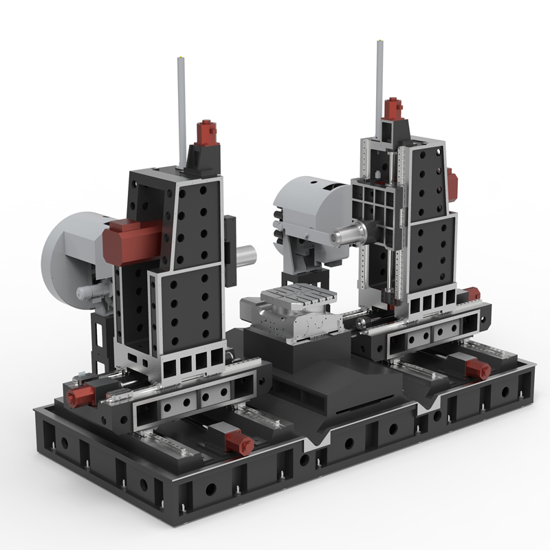
Parts processing horizontal machining center
A horizontal machining center is a machining center machine tool with the spindle axis set parallel to the worktable. It can process larger parts and has the ability to perform indexed rotary processing....
A horizontal machining center is a machining center machine tool with the spindle axis set parallel to the worktable. It can process larger parts and has the ability to perform indexed rotary processing. The horizontal machining center is most suitable for multi-process processing such as milling, drilling, boring, reaming, tapping, two-dimensional and three-dimensional curved surfaces of parts. The horizontal machining center can complete the box hole system and plane processing in one clamping , especially suitable for U-turn boring processing of box holes. In addition, horizontal machining centers are widely used in automobiles, internal combustion engines, aerospace, home appliances, general machinery and other industries.
Horizontal machining centers have some notable features. First of all, horizontal machining centers usually have 5 coordinate axes and are often equipped with a rotary axis (or rotary table). Secondly, the tool magazine capacity of horizontal machining centers is generally large, and some tool magazines can store hundreds of tools, which greatly improves the efficiency and flexibility of processing. However, the structure of the horizontal machining center is more complex than the vertical machining center, takes up a larger area, and is more expensive.
In terms of parts processing, horizontal machining centers are particularly suitable for processing parts such as boxes, especially for some holes and hole systems on box parts, as well as boxes with strict dimensional requirements for holes, cavities and datum planes. , can get a good guarantee. In addition, horizontal machining centers are also widely used in the aerospace field to produce various high-precision aviation parts, such as aircraft engine turbine blades, casings, bearing holes, etc.; as well as in the new energy field, they are used to produce high-precision aerospace parts. Component.
The working principle of the horizontal machining center is to use the relative motion of the spindle and the worktable to cut the workpiece. The main spindle of the horizontal machining center has the characteristics of high-speed rotation, driving the cutting tool to perform cutting; the worktable of the horizontal machining center moves in the horizontal direction to control the relative position and cutting path of the workpiece and the tool; the horizontal machining center is selected according to the workpiece material and processing requirements. Suitable cutting tools for cutting; at the same time, the application of coolant in horizontal machining centers helps to reduce the temperature, extend the service life of the cutting tools, clean the cutting area, and ensure the processing quality.
In general, the horizontal machining center is an efficient and flexible processing equipment that can meet the processing needs of a variety of complex parts. For more information, it is recommended to consult the relevant machine tool operating manual or consult a worker with experience in machine tool operation.
| Specifications/model | Unit | WHH50 | WHH63 | WHH80 | WHH100 |
| Work content | |||||
| Turntable table size WHA | MM | 500×500 | 630×630 | 800×800 | 1000×1000 |
| Fixed table size WHF (optional) | MM | 1000×500 | 1300×600 | 1300×600 | 1600×1000 |
| Number of worktables (optional translational double work) | N | Single/Double | Single/Double | Single/Double | Single/Double |
| Workbench indexing (standard) | N | 1 degree 1 minute | 1 degree 1 minute | 1 degree 1 minute | 1 degree 1 minute |
| Workbench (optional) | N | Other graduations can be customized | Other graduations can be customized | Other graduations can be customized | Other graduations can be customized |
| Maximum rotation diameter of worktable | MM | 1000 | 1300 | 1300 | 1600 |
| X1.X2 axis travel | MM | 800 | 1000 | 1000 | 1300 |
| Y1.Y2 axis travel (spindle item moves up and down) | MM | 700 | 700 | 700 | 700 |
| Z1.Z2 axis stroke | MM | 500 | 900 | 900 | 900 |
| Distance from spindle center to worktable | MM | 110-810 | 110-810 | 110-810 | 110-810 |
| Distance from spindle end face to worktable center | MM | 200-700 | 200-1100 | 200-1100 | 200-1100 |
| T-shaped workbench (slot width * number of slots) | MM | 22-3 | 22-3 | 22-5 | 22-5 |
| Workbench load-bearing | KG | 2000 | 2500 | 3200 | 5000 |
| Spindle and spindle box specifications | |||||
| Spindle taper hole (model/installation dimensions) | ISO | BT40-150 | BT50-190 | BT50-190 | BT50-190 |
| Spindle speed mark (optional) | RPM | 4000/8000/12000 | 4000/6000 | 4000/6000 | 4000/6000 |
| Feeding system | |||||
| X.Y.Z axis screw specifications | MM | 40/40/40 | 50/50/50 | 50/50/50 | 63/50/50 |
| X-axis rapid movement speed | M/MIN | X:48 | X:32 | X:32 | X:24 |
| Y-axis rapid movement speed | M/MIN | Y:48 | Y:32 | Y:32 | Y:24 |
| Z-axis rapid movement speed | M/MIN | Z:48 | Z:32 | Z:32 | Z:24 |
| X/Y/Z axis wire gauge specifications | MM | Roller 45/45/45 | Roller 55/55/55 | Roller 55/55/55 | Roller 55/55/55 |
| X/Y/Z motor connection method | / | direct connection | direct connection | direct connection | direct connection |
| main motor power | KW | 11 | 18.5 | 18.5 | 18.5 |
| X-axis motor power | NM | 22/22B/22 | 27/27B/27 | 27/27B/27 | 30/30B/30 |
| B-axis motor power | NM | B:8 | 12 | 12 | 22 |
| Axis positioning accuracy | MM | ±0.005/300 | ±0.005/300 | ±0.005/300 | ±0.005/300 |
| Axis item repeat positioning accuracy | MM | ±0.003/300 | ±0.003/300 | ±0.003/300 | ±0.003/300 |
| BPositioning accuracy | MM | 8” | 8” | 8” | 8” |
| B Repeat positioning accuracy | MM | 5” | 5” | 5” | 5” |
| Minimum move value | MM | 0.001 | 0.001 | 0.001 | 0.001 |
| Oil and gas pressure system | |||||
| air pressure | KG | 7 | 7 | 7 | 7 |
| coolant capacity | L | 550 | 650 | 650 | 850 |
| Lubricating oil capacity L | L | 4 | 4 | 4 | 4 |
| Toolholder/Tool Magazine System (specify when ordering) | |||||
| Tool magazine structure | / | Robotic arm | Robotic arm | Robotic arm | Robotic arm |
| Number of tool magazines | T | 24 | 24 | 24 | 24 |
| Tool changing time T-T | MM | 3 | 7 | 7 | 7 |
| Maximum tool weight | KGS | 8 | 12 | 12 | 12 |
| Form factor | |||||
| Weight approx. | KG | 10/11 | 19/20 | 21/22 | 28/30 |
| Machine length | MM | 5500 | 7500 | 7500 | 9500 |
| Machine width | MM | 3800 | 4500 | 4500 | 5500 |
| Machine height (maximum) | MM | 3300 | 3700 | 3700 | 4200 |
| Machine height (minimum) | MM | 3000 | 3300 | 3300 | 3600 |
| Chip removal method | / | win screw + single chain plate | win screw + double chain plate | win screw + double chain plate | win screw + double chain plate |

 English
 日本語
日本語 한국어
한국어 Россия
  Français
 España
 عرب .
عرب .  Português
 Deutsch
 भारत
भारत Нидерланды
