- contact us
- Sales Manager:
Asia Li - Email:
asia.cncmachine@gmail.com - Wechat ID:
Asia-Li_90727( +8613210773378) TEL:+8613210773378 - TEL:
8613210773378 - Whatsapp:
8613210773378
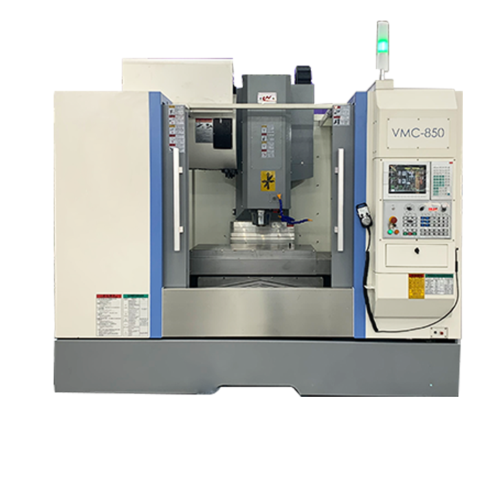
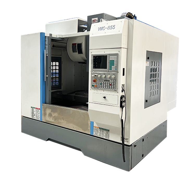
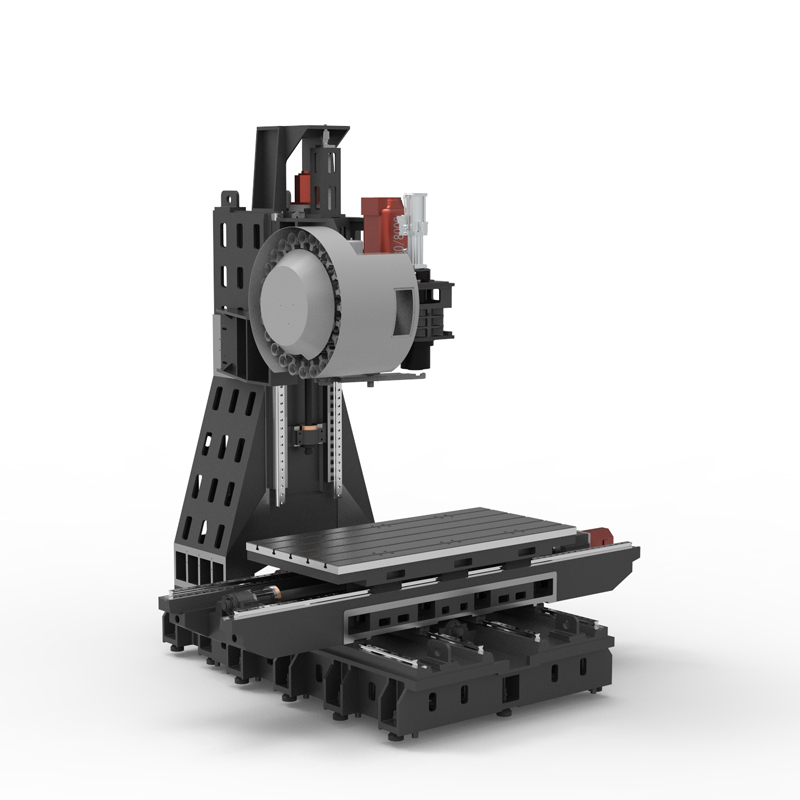
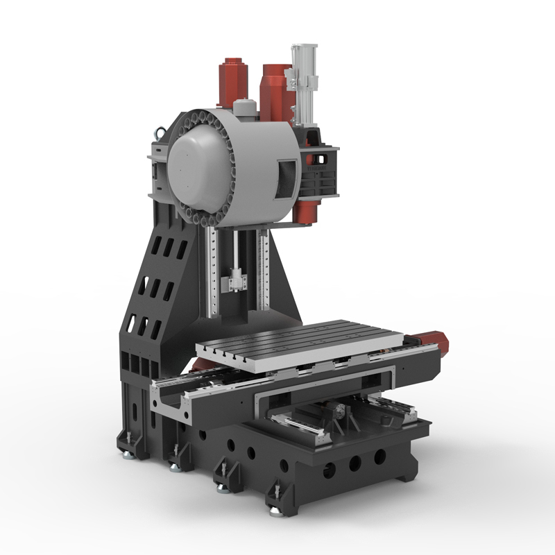
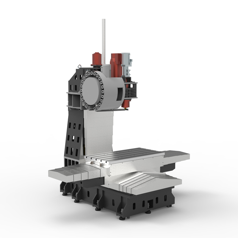
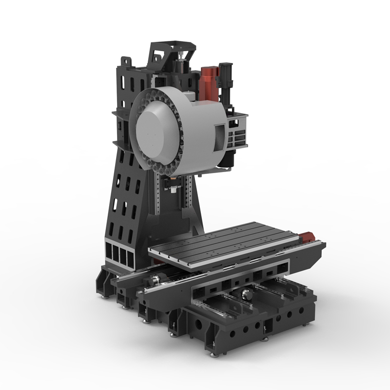
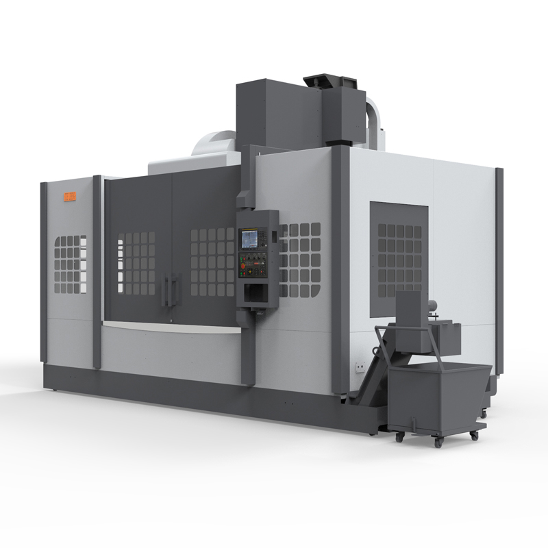
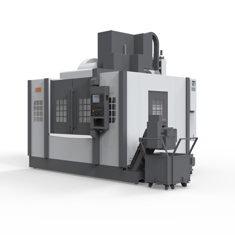
Drilling and milling integrated machining center
The drilling and milling integrated machining center is a multi-functional mechanical equipment that integrates drilling, milling and tapping....
The drilling and milling integrated machining center is a multi-functional mechanical equipment that integrates drilling, milling and tapping. It adopts advanced CNC technology and integrates two processing methods: drilling machine and milling machine. It has the characteristics of high speed, high precision and high stability, and can realize efficient processing technology and improve production efficiency.
The integrated drilling and milling machining center can complete multiple processing operations at the same time, greatly shortening the production cycle and improving product quality. The integrated drilling and milling machining center has significant advantages. The integrated drilling and milling machining center can not only perform high-speed cutting and greatly shorten the processing time, but also realize the processing of multiple processes in one clamping through the automation function, reducing the need for manual intervention and control, and further improving work efficiency.
In addition, the integrated drilling and milling machining center also has good processing accuracy and stability, and can ensure product quality and accuracy requirements. Drilling and milling integrated machining centers are widely used in aerospace, automobile manufacturing, electronic equipment, precision machinery and other industries, providing enterprises with efficient and precise processing solutions.
However, it should be noted that the integrated drilling and milling machining center is mainly used for processing light and small metals and may not be suitable for heavy cutting. In addition, when using the integrated drilling and milling machining center, correct operating methods and precautions need to be followed to ensure the safe operation of the equipment and processing quality.
In general, the integrated drilling and milling machining center is an efficient and precise processing equipment with wide application prospects. With the continuous advancement of technology, this equipment will continue to play an important role in the manufacturing field and create more value for enterprises.
| Specifications/model | unit | V640 | V840 | V850 | V1050 | V855 | V858 | V875 | V878 |
| Work content | |||||||||
| working desk size | MM | 700×400 | 1000×400 | 1000×500 | 1100×500 | 1000×550 | 1000×550 | 1000×700 | 1000×700 |
| Workbench travel (X/Y/Z) | MM | 600×400×400 | 800×400×400 | 800×500×500 | 1000×500×500 | 800×550×550 | 800×550×800 | 800×700×550 | 800×700×800 |
| Distance from spindle nose to work surface | MM | 150-550 | 150-550 | 150-650 | 150-650 | 150-700 | 150-950 | 150-700 | 150-950 |
| Distance from spindle center to column track surface | MM | 466 | 466 | 550 | 550 | 610 | 610 | 770 | 770 |
| Maximum load of workbench | KG | 350 | 400 | 500 | 800 | 600 | 600 | 700 | 700 |
| Spindle specifications | |||||||||
| Spindle transmission structure (standard) | / | Belt type | Belt type | Belt type | Belt type | Belt type | Belt type | Belt type | Belt type |
| Spindle speed | RPM | 10000 | 10000 | 10000 | 10000 | 8000 | 8000 | 8000 | 8000 |
| Spindle transmission structure (optional) | / | direct connection | direct connection | direct connection | direct connection | direct connection | direct connection | direct connection | direct connection |
| Spindle speed | RPM | 12000 | 12000 | 12000 | 12000 | 12000 | 12000 | 12000 | 12000 |
| Spindle power | KW | 5.5 | 5.5 | 7.5 | 7.5 | 11 | 11 | 11 | 11 |
| Spindle bore taper | BT | BT40-120 | BT40-120 | BT40-140 | BT40-140 | BT40-150 | BT40-150 | BT40-150 | BT40-150 |
| Feed content | |||||||||
| G00 rapid feed | M/MIN | 48/48/48 | 48/48/48 | 48/48/48 | 48/48/48 | 48/48/48 | 48/48/48 | 48/48/48 | 48/48/48 |
| G01 cutting feed | MM/MIN | 1-10000 | 1-10000 | 1-10000 | 1-10000 | 1-10000 | 1-10000 | 1-10000 | 1-10000 |
| Servo motor specifications | NM | 12/12/22B | 12/12/22B | 12/12/22B | 12/12/22B | 22/22/22B | 22/22/22B | 22/22/22B | 22/22/22B |
| Servo motor speed | RPM | 3000 | 3000 | 3000 | 3000 | 3000 | 3000 | 3000 | 3000 |
| Motor connection method | / | Direct | Direct | Direct | Direct | Direct | Direct | Direct | Direct |
| Ball screw specifications | MM | 3216 | 3216 | 4016 | 4016 | 4016/12 | 4016/12 | 4016/12 | 4016/12 |
| X-axis rail specifications | MM | 30 roller | 30 roller | 35 roller | 35 roller | 35 roller | 35 roller | 45 roller | 45 roller |
| Y axis rail specifications | MM | 30 roller | 30 roller | 35 roller | 35 roller | 35 roller | 35 roller | 45 roller | 45 roller |
| Z axis rail specifications | MM | 35 roller | 35 roller | 35 roller | 35 roller | 45*3 roller | 45*3 roller | 45*3 roller | 45*3 roller |
| Z-axis VB hard rail (optional) | / | / | / | / | / | hard rail | hard rail | hard rail | hard rail |
| Precise shaft positioning | MM | ±0.005/300 | ±0.005/300 | ±0.005/300 | ±0.005/300 | ±0.005/300 | ±0.005/300 | ±0.005/300 | ±0.005/300 |
| Repeatable positioning precision | MM | ±0.003/300 | ±0.003/300 | ±0.003/300 | ±0.003/300 | ±0.003/300 | ±0.003/300 | ±0.003/300 | ±0.003/300 |
| Minimum move value | MM | 0.001 | 0.001 | 0.001 | 0.001 | 0.001 | 0.001 | 0.001 | 0.001 |
| Tool magazine system | |||||||||
| Tool magazine structure | / | Knife arm type | Knife arm type | Knife arm type | Knife arm type | Knife arm type | Knife arm type | Knife arm type | Knife arm type |
| Tool magazine capacity | PCS | 16 | 16 | 24 | 24 | 24 | 24 | 24 | 24 |
| Tool changing time | MM | 2.2 | 2.2 | 2.2 | 2.2 | 2.2 | 2.2 | 2.2 | 2.2 |
| Maximum tool weight | KG | 8 | 8 | 8 | 8 | 8 | 8 | 8 | 8 |
| Oil and gas pressure system | |||||||||
| air pressure | KG/MM | 6.5-8 | 6.5-8 | 6.5-8 | 6.5-8 | 6.5-8 | 6.5-8 | 6.5-8 | 6.5-8 |
| Lubricating oil capacity | L | 4 | 4 | 4 | 4 | 4 | 4 | 4 | 4 |
| battery capacity | KW | 18 | 18 | 23 | 23 | 23 | 23 | 23 | 23 |
| coolant capacity | L | 220 | 220 | 250 | 250 | 250 | 250 | 250 | 250 |
| Form factor | |||||||||
| Machine weight (approx.) | T | 3.6 | 3.8 | 5.3 | 5.5 | 5.5 | 5.7 | 6.4 | 6.5-8 |
| Machine length (front and rear) | MM | 2150 | 2150 | 2400 | 2400 | 2600 | 2600 | 3000 | 3000 |
| Machine width (left and right) | MM | 2000 | 2200 | 2660 | 3060 | 3060 | 3060 | 3060 | 3060 |
| Machine height (maximum) | MM | 2700 | 2700 | 2700 | 2700 | 2800 | 3100 | 3100 | 3400 |
| Machine height (minimum) | MM | 2300 | 2300 | 2300 | 2300 | 2400 | 2600 | 2600 | 2600 |
| Chip removal method (optional) | / | single chain plate | single chain plate | single chain plate | single chain plate | single chain plate | single chain plate | single chain plate | single chain plate |
| Chip removal method (optional) | / | Twin screw | Twin screw | Twin screw | Twin screw | Twin screw | Twin screw | Twin screw | Twin screw |

 English
 日本語
日本語 한국어
한국어 Россия
  Français
 España
 عرب .
عرب .  Português
 Deutsch
 भारत
भारत Нидерланды
